Monobloc blade preform and module for a turbo machine intermediate casing

a technology of turbo machines and modules, applied in the direction of machines/engines, efficient propulsion technologies, other domestic articles, etc., can solve the problem of limited overall stiffness of such a module, and achieve the effect of reducing size and weight, increasing stiffness and thickness

Active Publication Date: 2018-11-20
SN DETUDE & DE CONSTR DE MOTEURS DAVIATION S N E C M A
View PDF22 Cites 1 Cited by
  • Summary
  • Abstract
  • Description
  • Claims
  • Application Information

AI Technical Summary

Benefits of technology

[0012]Using such a preform, it is possible to design a single-piece module made up of at least two vanes that are connected together at one of their ends: such a single-piece configuration enables mechanical loads to be distributed more effectively on the pair of vanes. This leads to increased overall stiffness of the module, thus enabling parts to be used that are less heavy, thereby achieving significant savings in operation. The use of composite materials also achieves significant weight savings compared with similar parts made of metal or of ceramic.
[0030]By means of this single-piece configuration incorporating at least two vanes and a transverse vane portion, the above-described advantages in terms of mechanical strength, weight, cost, ease of dismantling, and ease of preparation are all obtained.

Problems solved by technology

Nevertheless, even though the progress achieved by that solution is already significant, the overall stiffness of such a module is limited by the tangential junctions of the bolts.

Method used


Image

  • Monobloc blade preform and module for a turbo machine intermediate casing
  • Monobloc blade preform and module for a turbo machine intermediate casing
  • Monobloc blade preform and module for a turbo machine intermediate casing

Examples


second embodiment

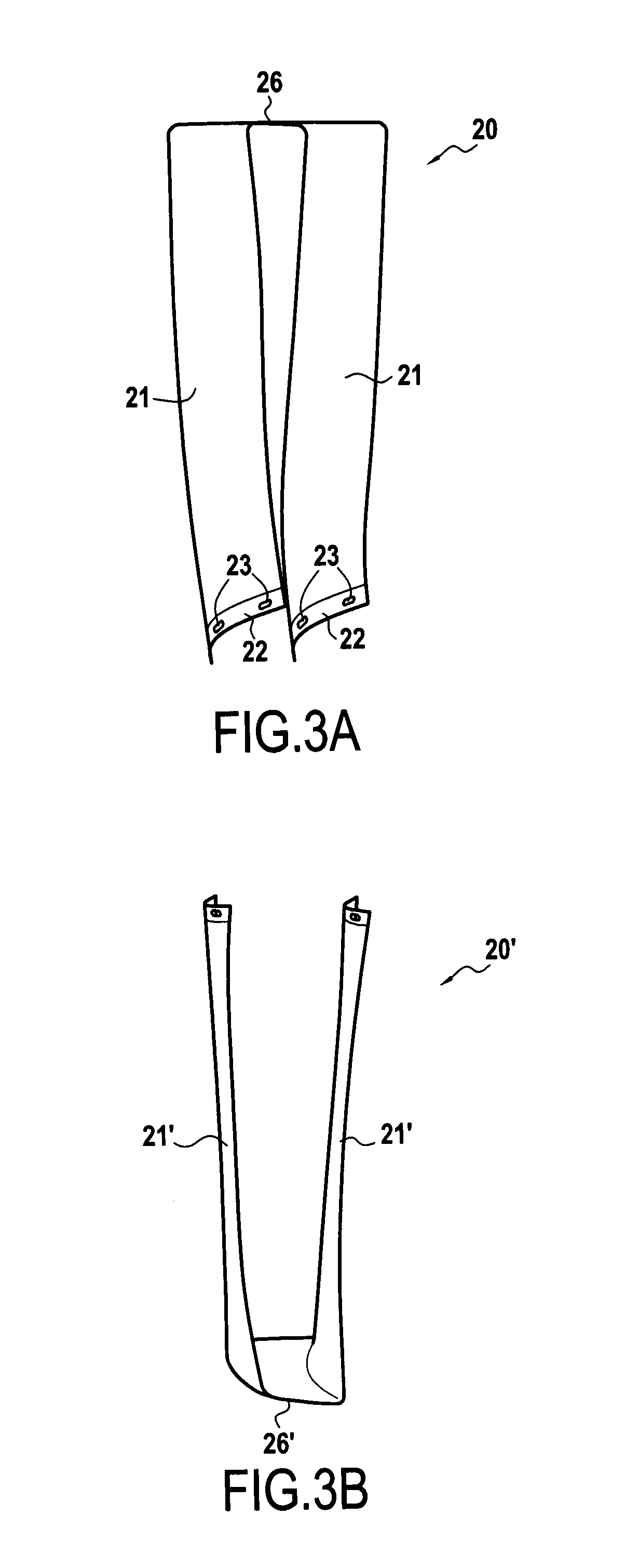
[0053]Depending on the type of fastening between the module 20 and the intermediate casing 10 via the transverse vane portion 26, this portion may be an aerodynamic platform constituting a smooth and aerodynamic wall for the secondary passage II of the turbine engine 1, or it may be a flange for fastening the module 20 to the intermediate casing 10. In particular, if the transverse vane portion 26 does not have any fastenings or has fastenings that are suitable for not projecting into the passage II, such as axial or tangential fastenings, the transverse vane portion 26 may act as a platform. In contrast, if the transverse vane portion 26 requires a fastening that projects into the passage II, in particular if it is a radial fastening, then the transverse vane portion 26 acts as a flange and an aerodynamic platform needs to be superposed on the transverse vane portion 26 in order to mask its fastenings. Such examples are described below with reference to the

[0054]In this embodiment,...

embodiment 20

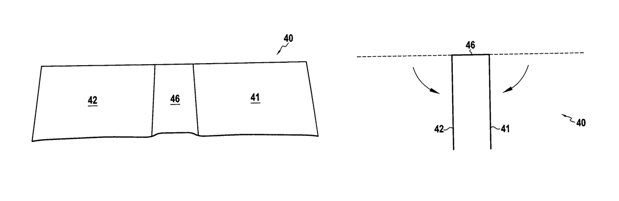
[0057]FIG. 3D shows the woven preform 40 laid out flat, which preform is used for making this first module embodiment 20. FIG. 3E shows how this preform 40 is shaped in order to obtain the module 20. Going from upstream to downstream, i.e. from right to left in the figures, this preform 40 comprises a first longitudinal segment 41, that is to form a first vane 21, a transverse segment 46 that is to form the transverse vane portion 26, and a second longitudinal segment 42 that is to form the second vane 21 of the module 20.

[0058]The preform 40 is taken from a 3D woven sheet of carbon fibers, made using a 3D interlock weave. Only the surfaces of the preform 40 are woven two-dimensionally (2D) with a satin type weave. In order to obtain vanes 21 that are fine and transverse vane portions 26 that are thicker, the transverse segment 46 of the preform 40 has a larger number of layers of yarns than do the longitudinal segments 41 and 42: methods of weaving that make it possible to obtain s...

embodiment 120

[0068]FIG. 4C shows the 3D woven preform 140 laid out flat, which preform is used for making this second module embodiment 120. FIG. 4D shows this preform 140 shaped in order to obtain the module 120. From upstream to downstream, i.e. from right to left in the figures, this preform 140 comprises a first transverse segment 146 that is to form a bottom transverse vane portion 127, a first longitudinal segment 141 that is to form a first vane 121, a second transverse segment 147 that is to form the top transverse vane portion 126, a second longitudinal segment 142 that is to form the second vane 121, and a third transverse segment 148 that is to form the second bottom transverse vane portion 127 of the module 120.


PUM

PropertyMeasurementUnit
thicknessaaaaaaaaaa
stiffnessaaaaaaaaaa
thrustaaaaaaaaaa

Abstract

A fiber preform for a vane module of an intermediate casing of a turbine engine, the preform being obtained by three-dimensional weaving. The preform includes first longitudinal segment presenting opposite first and second ends and suitable for forming a first vane; a second longitudinal segment presenting first and second opposite ends and suitable for forming a second vane; and a first transverse segment connecting together the first and second longitudinal segments by their first ends, and suitable for forming a first transverse vane portion such as a flange or a platform.

Description

FIELD OF THE INVENTION[0001]The present specification relates to a fiber preform for a vane module made of composite material for an intermediate casing of a turbine engine, and also to a single-piece vane module, an intermediate casing, and a turbine engine, as obtained thereby.[0002]Such a preform may be used to make single-piece vane modules each incorporating a plurality of vanes together with transverse vane portions such as flanges or aerodynamic platforms. Such modules present considerable stiffness and are suitable for incorporating in the intermediate casing of an airplane turbojet, for example.STATE OF THE PRIOR ART[0003]A conventional bypass turbojet has a fan delivering a stream of air that is split into both a primary stream that is directed to the compressors, the combustion chamber, and then the turbines of the turbine engine, and also a secondary or bypass stream that delivers the major fraction of the thrust.[0004]The secondary stream flows in a secondary passage pr...

Claims


Application Information

Patent Timeline
Patent Type & Authority Patents(United States)
IPC IPC(8): F01D9/04B29B11/16F01D5/28F01D5/14B29L31/08
CPCB29B11/16F01D5/146F01D5/282F01D9/042Y02T50/673B29L2031/087F05D2300/603Y02T50/672Y02T50/60
Inventor GIMAT, MATTHIEUCOUPE, DOMINIQUEMARCHAL, YANNPAPIN, THIERRY
Owner SN DETUDE & DE CONSTR DE MOTEURS DAVIATION S N E C M A
Why Eureka
Try Eureka