
Method of cutting liquid crystal display panel

a technology of liquid crystal display panel and cutting method, which is applied in non-linear optics, instruments, optics, etc., can solve the problems of loss of adherence to the mother substrate, and achieve the effect of minimizing the length of the bezel

Active Publication Date: 2018-11-27
SAMSUNG DISPLAY CO LTD
View PDF14 Cites 0 Cited by
  • Summary
  • Abstract
  • Description
  • Claims
  • Application Information

AI Technical Summary

Benefits of technology

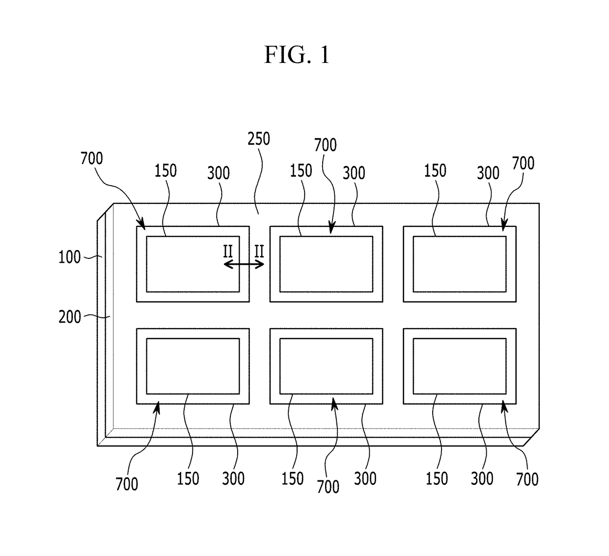
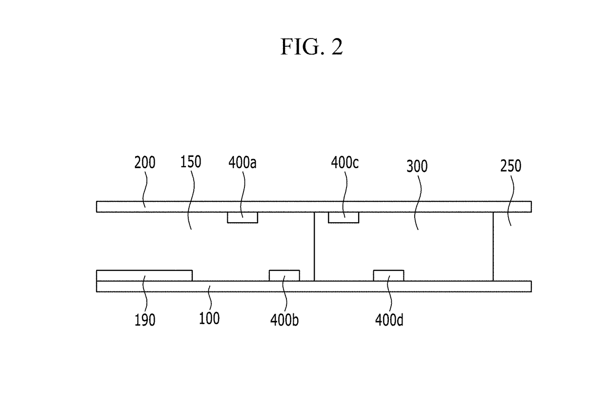
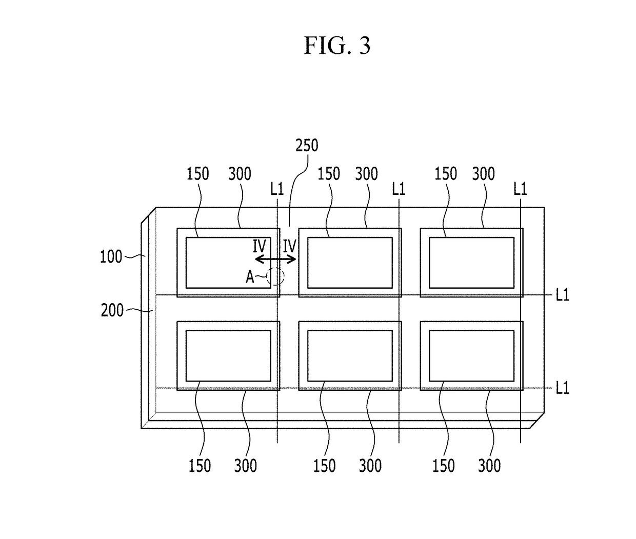
The present invention introduces a cutting method for liquid crystal panels that minimizes the bezel, prevents cracking of the incision surface, and prevents gas from flowing into the display area. This is achieved by firstly forming an empty space through laser irradulation at the region close to the dummy region of the sealant, which prevents gas generated during laser irradiation from flowing inside the display area. This method utilizes a cutting wheel and laser irradiation to precisely incise the panel and sealant, resulting in a more efficient and effective production process.

Problems solved by technology

The first irradiation line and the second irradiation line may be empty spaces in which the sealant is removed or spaces in which the sealant is partially removed or damaged such that adherence with the mother substrate is lost.

Method used


Image

  • Method of cutting liquid crystal display panel
  • Method of cutting liquid crystal display panel
  • Method of cutting liquid crystal display panel

Examples


Embodiment Construction

[0069]The present invention will be described more fully hereinafter with reference to the accompanying drawings, in which exemplary embodiments of the invention are shown. As those skilled in the art would realize, the described embodiments may be modified in various different ways, all without departing from the spirit or scope of the present invention.

[0070]In the drawings, the thickness of layers, films, panels, regions, etc., are exaggerated for clarity. Like reference numerals designate like elements throughout the specification. It will be understood that when an element such as a layer, film, region, or substrate is referred to as being “on” another element, it can be directly on the other element or intervening elements may also be present. In contrast, when an element is referred to as being “directly on” another element, there are no intervening elements present.

[0071]Now, a cutting method of a liquid crystal panel according to an exemplary embodiment of the present inven...


PUM

PropertyMeasurementUnit
distanceaaaaaaaaaa
widthaaaaaaaaaa
lengthaaaaaaaaaa

Abstract

A mother substrate assembly according to an exemplary embodiment of the present invention includes: a first mother substrate and a second mother substrate formed with a plurality of unit liquid crystal panels; and a sealant formed between the first mother substrate and the second mother substrate and combining the mother substrates, wherein the sealant encloses a circumference of each unit liquid crystal panel, and includes a first irradiation line formed in the sealant, and a second irradiation line formed in the sealant of a side closer to the unit liquid crystal panel than the first irradiation line.

Description

CLAIM OF PRIORITY[0001]This application claims priority to and the benefit of Korean Patent Application No. 10-2014-0092003 filed in the Korean Intellectual Property Office on Jul. 21, 2014, the entire contents of which are incorporated herein by reference.BACKGROUND OF THE INVENTION[0002]1. Field of Disclosure[0003]The present invention relates to a cutting method of a liquid crystal panel.[0004]2. Description of the Related Art[0005]Recently, displays visually processing and displaying a large amount of information have been quickly developed according to advances of the information age, and in response to this trend, various flat panel displays have been developed and spotlighted.[0006]As examples of the flat panel displays, there are a liquid crystal display (LCD), a plasma display panel (PDP), a field emission display (FED), and an electroluminescent display (ELD), and these flat panel displays having excellent characteristics such as thinness, light weight, and low power consu...

Claims


Application Information

Patent Timeline
Patent Type & Authority Patents(United States)
IPC IPC(8): G02F1/1339G02F1/1333
CPCG02F1/133351G02F1/1339
Inventor KIM, MIN SUKIM, JANG-HYUNKANG, TAE WOOKCHA, TAE WOON
Owner SAMSUNG DISPLAY CO LTD
Learn More