Combat vehicle seat installation for protection of occupants from the effects of ground explosions

a technology for vehicle seats and ground explosions, applied in vehicle seats, vehicle arrangements, vehicle components, etc., to achieve the effect of reducing the peak force and avoiding excessive spine compression

Inactive Publication Date: 2018-12-11
MANI AYYAKANNU
View PDF34 Cites 4 Cited by
  • Summary
  • Abstract
  • Description
  • Claims
  • Application Information

AI Technical Summary

Benefits of technology

[0013]The above object and other objects which will be understood by those skilled in the art are achieved by a seat installation comprised of three major components, which each reduce the chances of a serious injury to an occupant of the seat.
[0014]The first component is a breakaway connecting support of the seat pan on the vehicle floor, which initially is fully intact to briefly allow a direct transmission of the g forces into the seat pan in order to accelerate the seat sharply at the very beginning of the explosive blast. This support causes rapid initial upward acceleration of the seat pan, but which connecting support collapses quickly by a fracturing of the support, so as to avoid injury to the occupant by continuing of the initial acceleration.
[0016]Continued acceleration causes each plate section to completely fracture along the connection to the seat pan and floor allowing the two sections to collapse. This effectively insures removal of any structural connection between the seat pan and the floor through by the collapsed V plates.
[0017]The V plates thus cause a sharp acceleration the seat pan for a very brief initial interval, but that interval is short enough such that the movement of the seat pan is substantially taken up by the compression of soft tissues and some bone joints to thereby avoid excessive compression of the spine. This initial sharp movement has been determined to lower the peak forces causing spinal compression that would otherwise be generated.
[0018]The seat pan is thus caused to be briefly accelerated as much as possible without causing injury to the occupant.
[0022]The pivoting of the foot rest avoids tipping of the seat while allowing upward movement to avoid contact with the floor moving rapidly up as a result of the explosion.

Problems solved by technology

Continued acceleration causes each plate section to completely fracture along the connection to the seat pan and floor allowing the two sections to collapse.

Method used


Image

  • Combat vehicle seat installation for protection of occupants from the effects of ground explosions
  • Combat vehicle seat installation for protection of occupants from the effects of ground explosions
  • Combat vehicle seat installation for protection of occupants from the effects of ground explosions

Examples


Embodiment Construction

[0035]In the following detailed description, certain specific terminology will be employed for the sake of clarity and a particular embodiment described in accordance with the requirements of 35 USC 112, but it is to be understood that the same is not intended to be limiting and should not be so construed inasmuch as the invention is capable of taking many forms and variations within the scope of the appended claims.

[0036]The present invention was developed using performing nonlinear, dynamic analysis of the seat under blast conditions using the LS-DYNA software and specialized models of the Hybrid III crash dummies. The performance described below is based on that analysis.

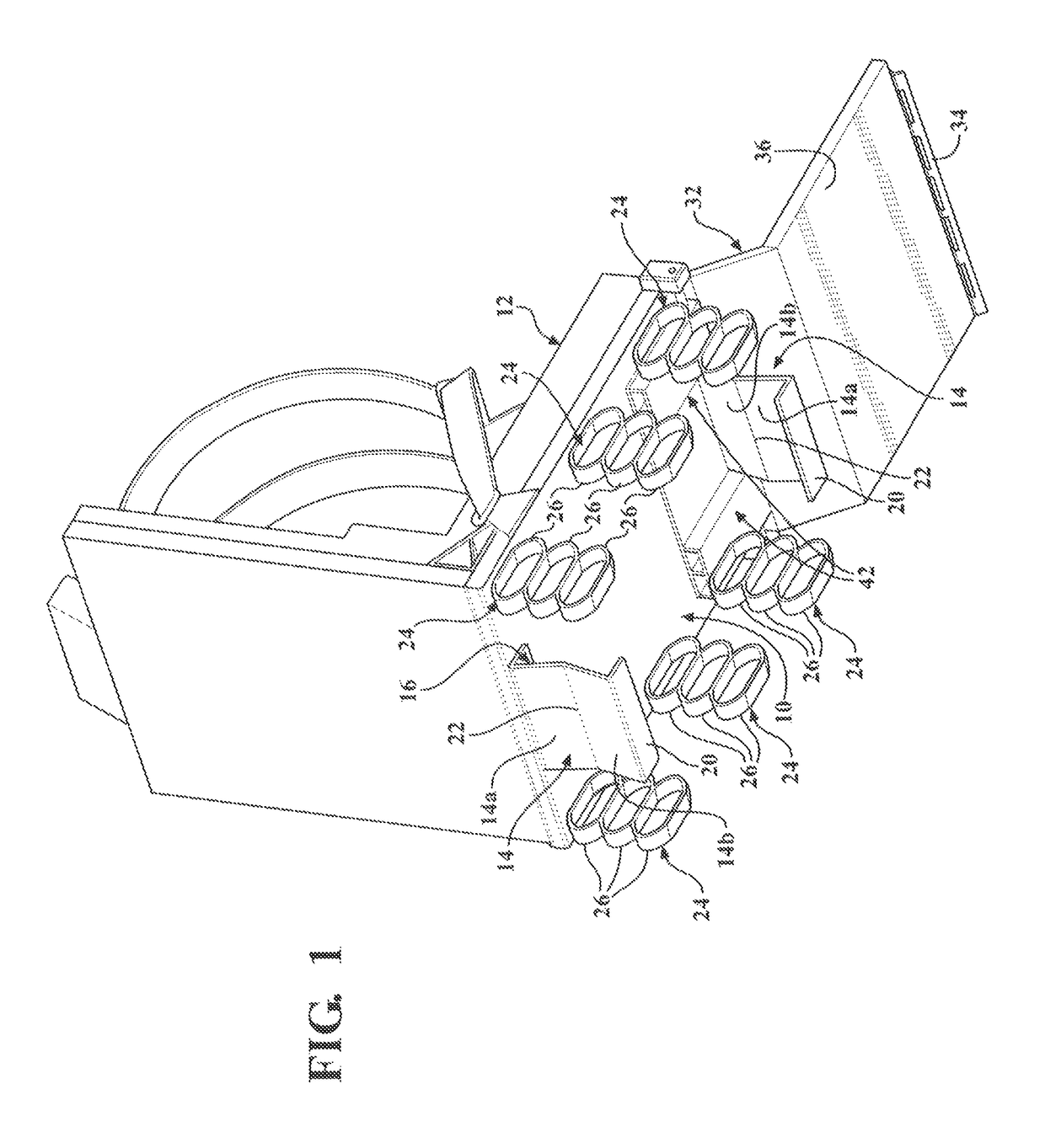
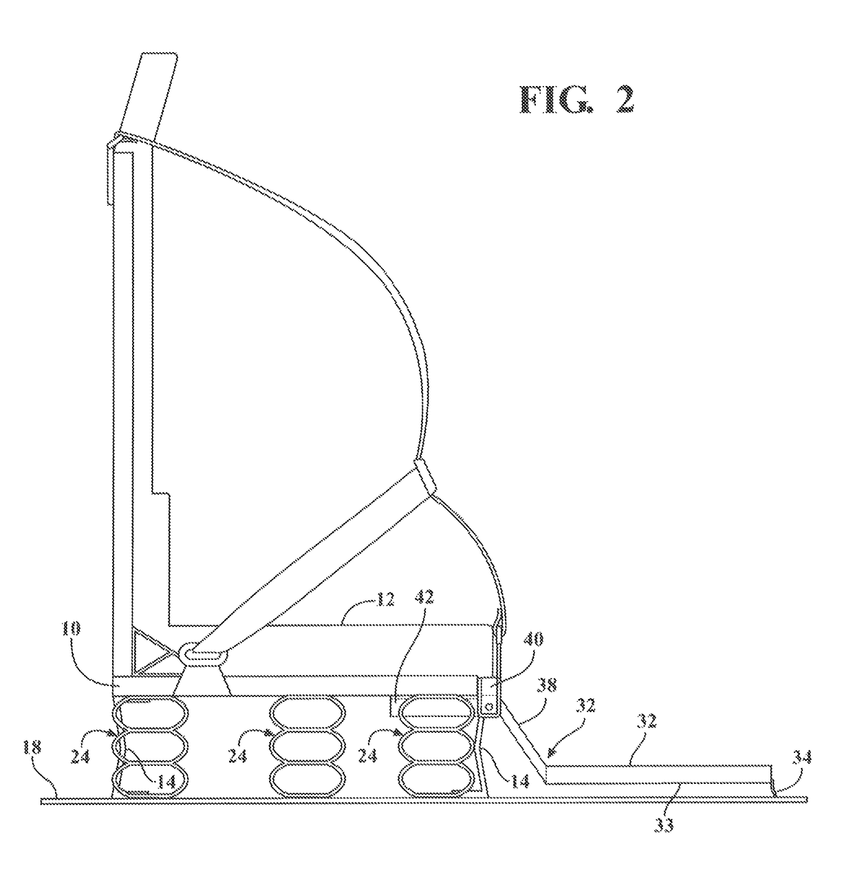
[0037]Referring to FIGS. 1 and 2 the combat vehicle seat installation of the present invention includes vehicle floor mounting components for a seat floor pan 10, which holds a seat cushion 12 on which an occupant sits. These components include a breakaway support structure 14 which directly connects the vehicle ...


PUM


Abstract

A seat installation for a combat vehicle which protects an occupant from the effects of an explosion detonated beneath the vehicle in which breakaway structures are interposed between a seat pan and the vehicle floor which initially rapidly drives the seat up after the explosion, but which quickly breaks away to avoid spinal compression injury. A crushable energy absorbing structures thereafter absorb the floor motion, each structure comprised with a vertical stack of crushable energy absorbing cells which are successively crushed at higher force levels to adapt the seat installation to varying weight occupants. A pivoted foot rest provides spaced above the floor which mitigates injuries to the feet and legs by allowing the feet to avoid contact with the floor and which swing up and away from the floor while avoiding tipping of the seat.

Description

CROSS REFERENCE TO RELATED PATENT APPLICATIONS[0001]This application claims the benefit of U.S. provisional application No. 62 / 299,040, filed on Feb. 24, 2016.STATEMENT REGARDING FEDERALLY SPONSORED RESEARCH OR DEVELOPMENT[0002]This invention was made with Government support under Contract W56HZV-15-C-0194 awarded by U.S. Army Tank Automotive Research Development and Engineering Center, Warren, Mich. The Government has certain rights in the invention.BACKGROUND OF THE INVENTION[0003]Combat ground vehicles such as tanks, personnel carriers, and Bradley combat vehicles are vulnerable to mines of other explosive devices buried in the ground, which creates an upward blast when detonated, imposing very high upwardly directed forces on the vehicle, which may seriously injure or kill the seated occupants.[0004]When the vehicle drops back down and impacts the surface, lower forces are imposed on the occupants.[0005]While the vehicle structures have been designed to withstand such blasts, th...

Claims


Application Information

Patent Timeline
Patent Type & Authority Patents(United States)
IPC IPC(8): B60N2/42B60N2/427B60N2/38
CPCB60N2/42709B60N2/42781B60N2/4242B60N2/38B60N2/24B60N2/42736B60N2/42754B60N3/066
Inventor MANI, AYYAKANNU
Owner MANI AYYAKANNU
Why Eureka
Try Eureka