Wiring box fixing structure for ventilating fan

a technology for fixing structure and ventilating fans, which is applied in the direction of pump components, liquid fuel engine components, non-positive displacement fluid engines, etc., can solve the problems of needing too much working time, and achieve the effects of reducing components, simplifying operating steps, and reducing time consumption

Active Publication Date: 2018-12-11
PANASONIC ECOLOGY SYSTEMS GUANGDONG CO LTD +1
View PDF8 Cites 0 Cited by
  • Summary
  • Abstract
  • Description
  • Claims
  • Application Information

AI Technical Summary

Benefits of technology

[0009]An object of this disclosure is to provide a ventilating fan that has reduced components and can simplify operating steps during fixing the wiring box on the casing, and is thereby less time consuming.
[0011]An advantage of the ventilating fan in this disclosure lies in that, while preventing a user from detaching the wiring box manually, the ventilating fan has reduced components and can simplify operating steps during fixing the wiring box on the casing, and is thereby less time consuming.

Problems solved by technology

However, the existing structure for fixing the wiring box 8 on the casing 4 has a problem of needing too much working hour due to many components and complicated operating steps.

Method used


Image

  • Wiring box fixing structure for ventilating fan
  • Wiring box fixing structure for ventilating fan
  • Wiring box fixing structure for ventilating fan

Examples


first embodiment

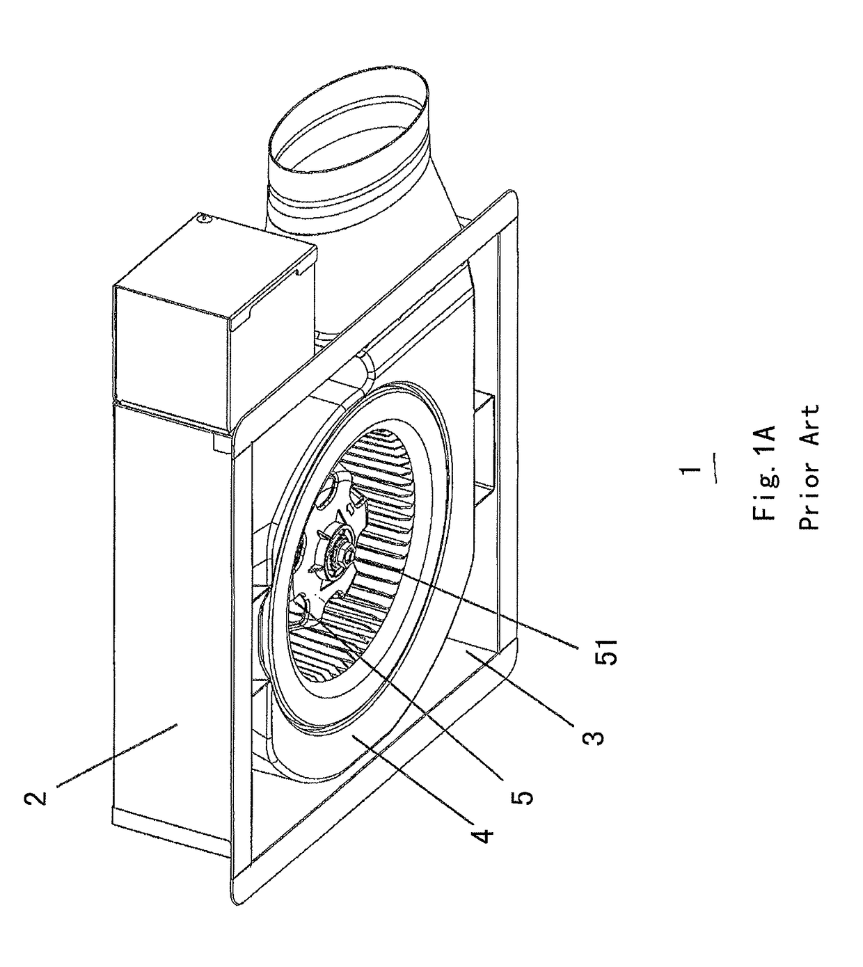
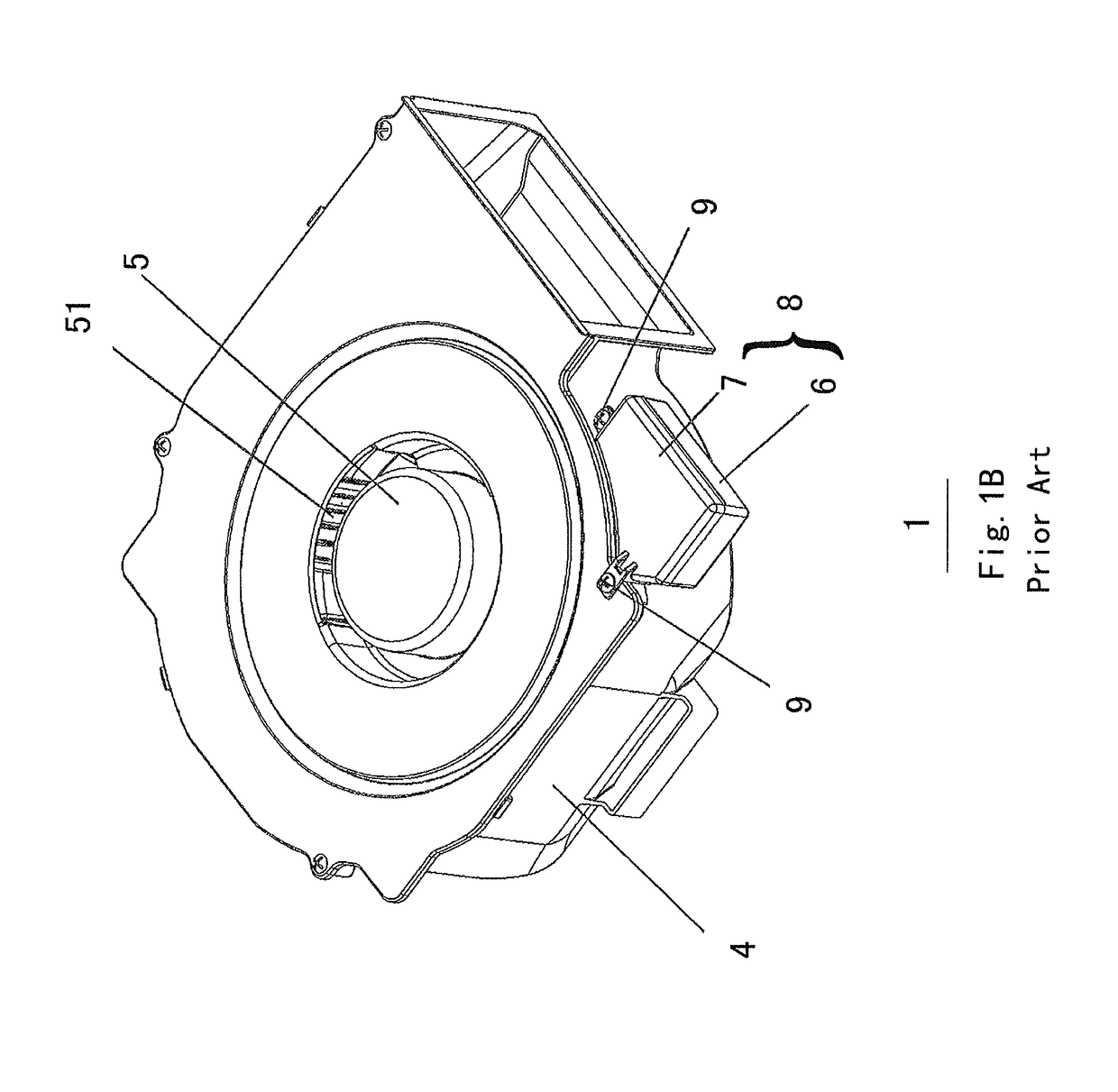
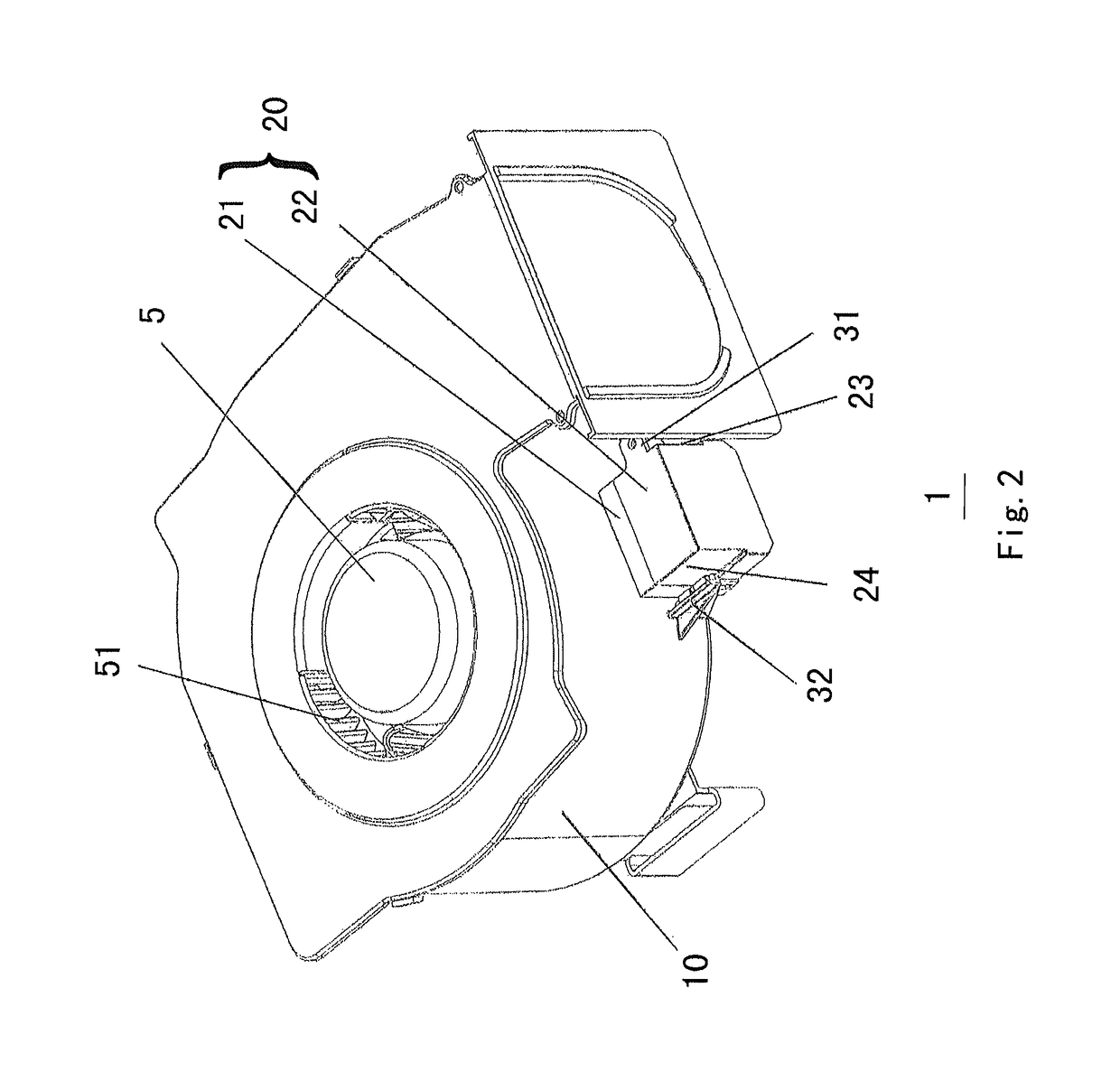
[0029]As shown in FIGS. 2, 3 and 4, the ventilating fan 1 according to the invention comprises: a housing (not shown) having an opening at a bottom surface thereof, a casing 10 disposed in the housing (not shown), fan blades 51 and a motor 5 disposed in the casing 10, and a wiring box 20 fixed on the casing 10 and composed of a box body 21 and a cover 22. The wiring box 20 is fixed on the casing 10 through a fixing structure, and the fixing structure comprises a first fixing means 31 and a second fixing means 32, the first fixing means 31 comprises a threaded fixing structure, and the second fixing means 32 comprises an engaging fixing structure.

[0030]With the above configuration, when the wiring box 20 is fixed onto the casing 10, firstly, the second fixing means 32 is fixed through an engaging fixing structure, then the first fixing means 31 is fixed through a screw fixing structure, such that the wiring box 20 is fixed on the casing 10.

[0031]When the wiring box 20 is fixed on the...

second embodiment

[0049]Specifically, in the second embodiment, the first rib 12 is provided with a second protuberance 122 on a horizontal bottom surface 252 thereof in the vertical direction, a third rib 27 is provided with a second cutout 262 engaging with the second protuberance 122 on the first rib 12, and the positional relationship between the wiring box 20 and the casing 10 meets the following conditions:

L1L2,

and

L2−L1=L32,

[0050]wherein, L1 is a distance from a central line 251 of the hole 250 in the first boss 25 of the wiring box 20 to an outmost edge of the first end 23 of the wiring box 20, L2 is a distance from a central line 111 of the hole 110 in the second boss 11 of the casing 10 to a side wall 101 of the casing 10, and L32 is a width of the first rib 12 of the third boss 13 of the casing 10 extending inwards, that is, towards the second boss 11.

[0051]The positional relationship also meets the following conditions:

L4>L5,

and

L4−L5=L32,

[0052]wherein, L4 is a distance from the central ...

third embodiment

[0059]Specifically, the engaging fixing structure of the second fixing means 32 in the third embodiment comprises: a fourth rib 42 disposed on the second end 24 of the wiring box 20, and a second recess 45 formed on the casing 10 at a position corresponding to the fourth rib 42, the fourth rib 42 and the second recess 45 are engage with each other.

[0060]The fourth rib 42 is formed at the second end 24 of the wiring box 20 and protruded outwards, a fourth boss 14 is provided on the casing 10 at a position corresponding to the fourth rib 42 and protruded outwards, the second recess 45 is formed by a gap between a fifth rib 46 and a sixth rib 28, both of which are formed on the fourth boss 14 and protruded outwards, and the fourth rib 42 is movable within the second recess 45.

[0061]With the above configuration, when the wiring box 20 is fixed onto the casing 10, the second fixing means 32 is firstly fixed, and then the first fixing means 31 is fixed. Specifically, firstly, the fourth r...


PUM


Abstract

A ventilating fan, includes a housing having an opening at a bottom surface thereof, a casing disposed in the housing, fan blades and a motor disposed in the casing, and a wiring box fixed on the casing and composed of a box body and a cover. The wiring box is fixed on the casing through a fixing structure, the fixing structure includes a first fixing means and a second fixing means, and the first fixing means includes a screw fixing structure, and the second fixing means includes an engaging fixing structure. An advantage of the ventilating fan lies in that, while preventing a user from detaching the wiring box manually, the ventilating fan has reduced components and can simplify operating steps during fixing the wiring box on the casing, and is thereby less time consuming.

Description

CROSS-REFERENCE TO RELATED APPLICATION[0001]This application claims the benefit of the Chinese Patent Application No. 201420644754.6 filed on Oct. 31, 2014 in the State Intellectual Property Office of China, the whole disclosure of which is incorporated herein by reference.BACKGROUND OF THE INVENTION[0002]Field of the Invention[0003]This disclosure relates to a ventilating fan, and specifically, to a fixing structure for a wiring box of a ventilating fan.[0004]Description of the Related Art[0005]FIG. 1A is an overall schematic view of an existing ventilating fan; FIG. 1B is a schematic view showing the installation between a casing and a wiring box in the existing ventilating fan.[0006]The existing ventilating fan 1 comprises: a housing 2 having an opening 3 at a bottom surface thereof, a casing 4 disposed in the housing 2, fan blades 51 and a motor 5 disposed in the casing 4, and a wiring box 8 fixed on the casing 4 and composed of a box body 6 and a cover 7, the wiring box 8 being...

Claims


Application Information

Patent Timeline
Patent Type & Authority Patents(United States)
IPC IPC(8): F04D25/06F04D29/42F04D25/08F04D29/62
CPCF04D25/0693F04D29/626F04D29/4226F04D25/08
Inventor LIANG, QIUQIANARAKI, NAOYASUZUKI, MASATO
Owner PANASONIC ECOLOGY SYSTEMS GUANGDONG CO LTD
Why Eureka
Try Eureka