Utility Knife

Active Publication Date: 2022-03-03
WANG AIGUO
View PDF0 Cites 1 Cited by
  • Summary
  • Abstract
  • Description
  • Claims
  • Application Information

AI Technical Summary

Benefits of technology

[0051]In order to guide the sliding of the position control component, preferably, the housing has a first chute communicated with the chamber and disposed on a side surface; the head of the position control component is disposed in the first chute, and the first chute is used for guiding the sliding of the position control component; the slide rail is located on the inner wall corresponding to the first chute. Guided by the first chute, the position control component can slide quickly.
[0052]In order to guide the sliding of the safety control component, preferably, the housing has a second chute communicated with the chamber and disposed on a top surface; the head of the safety control component is disposed in the second chute, and the second chute is used for guiding the sliding of the safety control component; the extension length of the second chute corresponds to the extension length of the first chute. Guided by the second chute, the safety control component can slide quickly.
[0053]Compared with the prior art, the present invention has the following beneficial effects: in the positioning direction, the fi

Problems solved by technology

However, this patent has the following problems.
Thus, the utility knife has many parts, resulting in high material cost, and many assembly steps and time-consuming assembly process.
Second, the pin shaft and the pin hole or the lock plate and the lock tongue are small in size, high assembly accuracy is required.
In the case of any slight misalignment in position, the pin shaft and the pin hole, or the lock plate and the lock tongue, cannot be well interlocked, consequently the interlock structure is invalid.
In addition, the pin shaft and the lock tongue of the interlock structure are easy to lose due to their small size.
Consequently, the blade on the blade carrier w

Method used


Image

  • Utility Knife
  • Utility Knife
  • Utility Knife

Examples


Embodiment Construction

[0073]The present invention will be further described below in detail with reference to the accompanying drawings by embodiments.

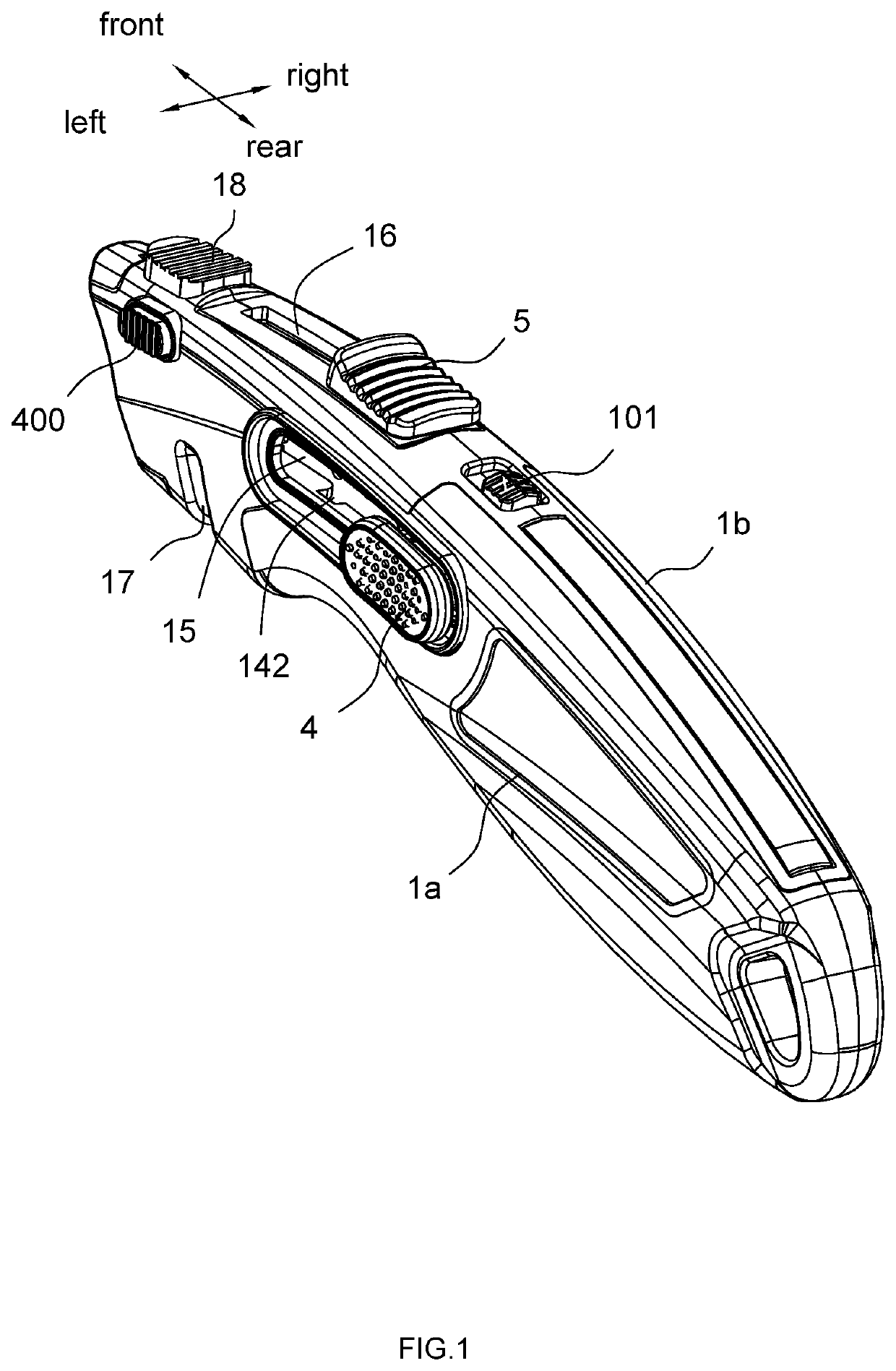
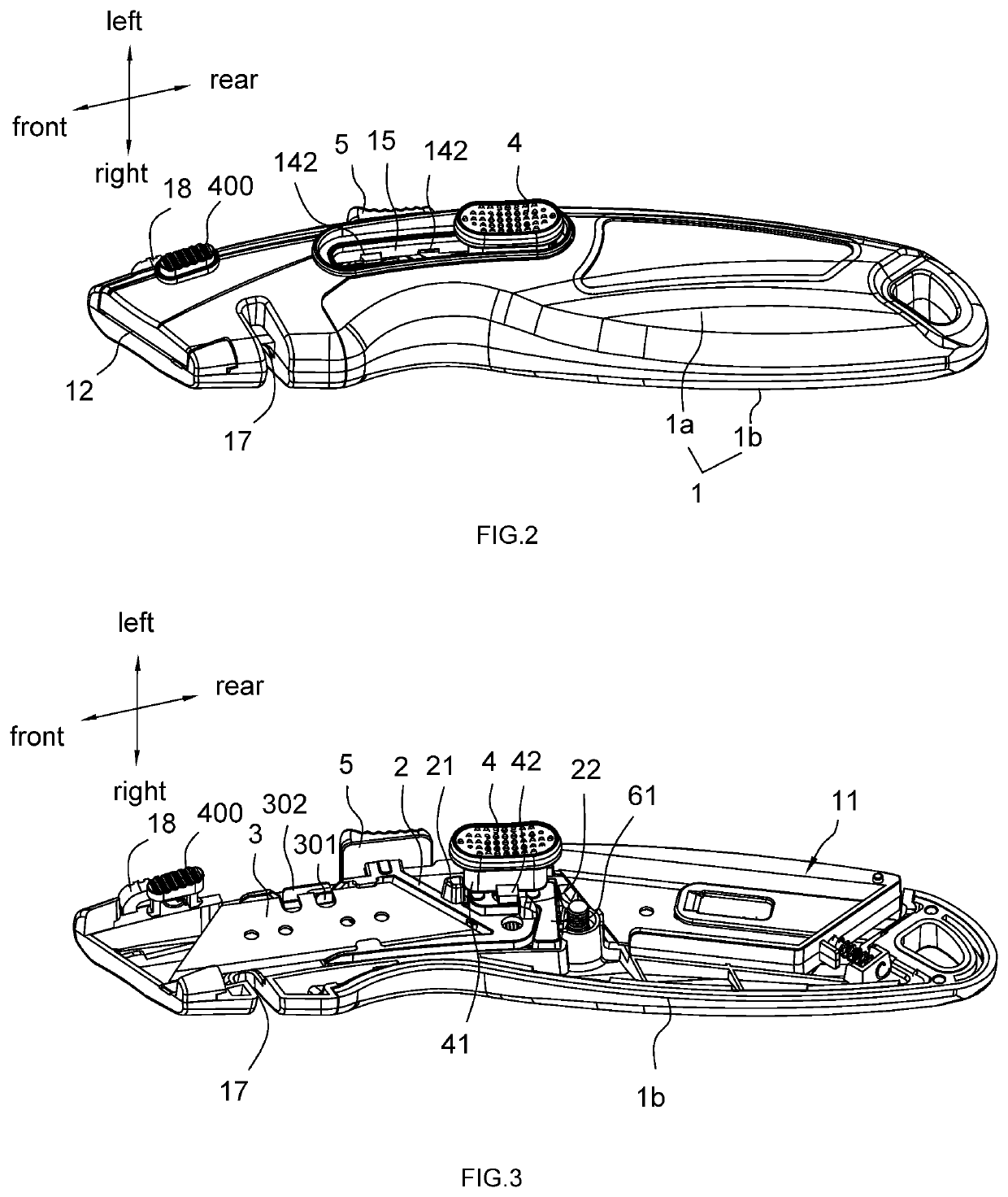
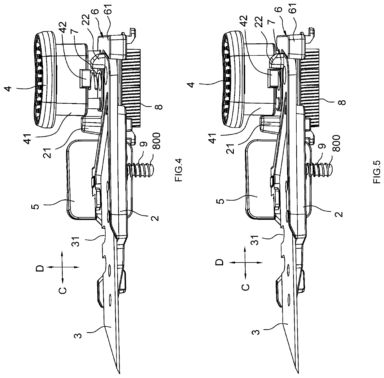
[0074]FIGS. 1 to 18 show a preferred embodiment of the utility knife of the present invention.

[0075]The utility knife comprises main components such as a housing 1, a blade carrier 2, a blade 3, a position control component 4, a safety control component 5, a first elastic component 7, and a second elastic component 8.

[0076]The housing 1 comprises a chamber 11, a front opening 12 communicated with the chamber 11, a slide rail 13 disposed in the chamber 11 for the position control component 4 to slide, a first chute 15 communicated with the chamber 11, a second chute 16 communicated with the chamber 11, and a rubber force-application portion 18 on the top. In order to facilitate the installation, the housing 1 comprises a left housing 1a and a right housing 1b that can be folded together. The left housing 1a and the right housing 1b are folded to form the ch...


PUM


Abstract

A utility knife comprises a housing (1), a blade carrier (2), a blade (3), a position control component (4) and a safety control component (5); a positioning direction (B) is defined at an angle to the sliding direction (A) of the position control component (4), the first blocking position (141) is farther away from the positioning portion (42) of the position control component (4) than the rest areas of the slide rail (13) except the first blocking position (14). In this way, in addition to blocking position shift, the position control component can also be used for contact-fitting with the blade carrier to determine whether the blade carrier can slide forward independently. Therefore, the utility knife has fewer components, resulting in low material cost, fewer assembly steps, convenient and time-saving assembly process, and the components are not easy to lose.

Description

TECHNICAL FIELD OF THE INVENTION[0001]The present invention relates to the field of hand tools, in particular to a utility knife.BACKGROUND OF THE INVENTION[0002]The utility knife is a commonly used hand tool for cutting paper, leather, plastic sheets, cardboard, etc. The utility knife generally comprises a housing, a blade carrier, and a blade. The housing has an accommodating cavity and a front opening communicated with the accommodating cavity. The blade carrier is arranged in a sliding manner in the accommodating cavity of the housing, and the blade is arranged on the blade carrier and can go into and out of the front opening as the blade carrier slides.[0003]In order to overcome the problem that the blade does not retract automatically after its extension, solutions have been proposed. For example, Chinese Invention Patent CN102398272B disclosed a geared safety knife. The geared safety knife comprises an outer frame, a blade carrier, a blade, a push button, a blocking position ...

Claims


Application Information

Patent Timeline
IPC IPC(8): B26B5/00
CPCB26B5/003B25G1/08B26B1/08B26B5/001
Inventor WANG, AIGUO
Owner WANG AIGUO
Why Eureka
Try Eureka