Ecological soil remediation equipment

A technology of ecological soil and equipment, applied in the field of soil remediation, can solve the problems of inability to use centrifugal force and easy soil adhesion.

Inactive Publication Date: 2021-06-18
王鼎楠
View PDF7 Cites 0 Cited by
  • Summary
  • Abstract
  • Description
  • Claims
  • Application Information

AI Technical Summary

Problems solved by technology

[0005] Because the soil is easy to adhere to the outside of the restoration equipment, when this kind of restoration equipment drills the soil, the restoration equipment cannot prevent the soil from entering the interior of the restoration equipment through the liquid outlet hole, and the soil needs to be mixed evenly by adding liquid medicine during the restoration process , and this kind of repair equipment needs to manually open the valve, and cannot use the centrifugal force generated during the drilling process to automatically add the liquid medicine during the drilling process

Method used


Image

  • Ecological soil remediation equipment
  • Ecological soil remediation equipment
  • Ecological soil remediation equipment

Examples


Embodiment 1

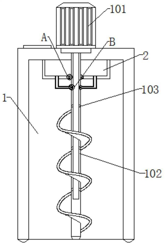
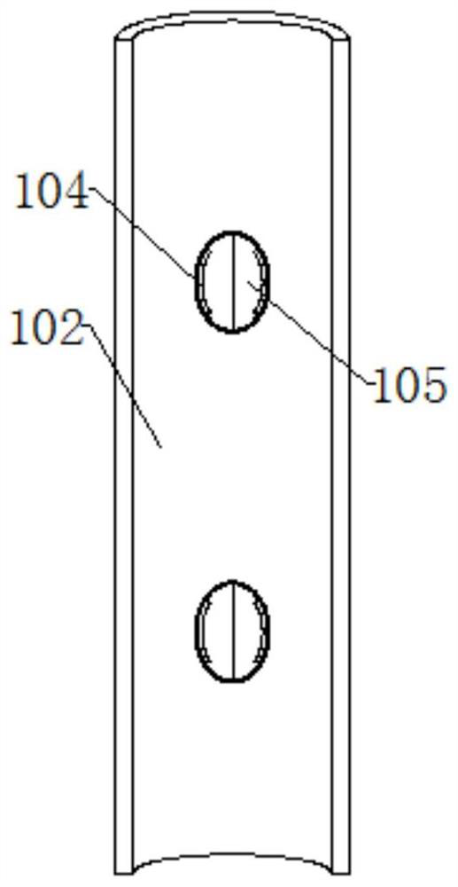
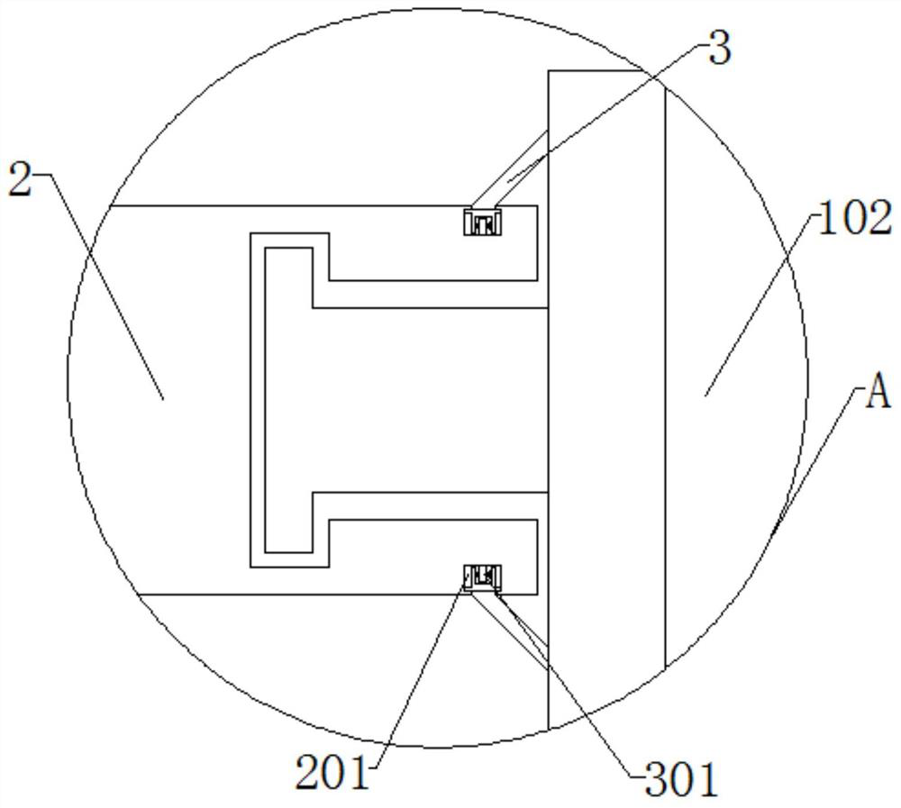
[0032] Embodiment 1: a motor 101 is installed on the upper end of the device main body 1, an auger 102 is rotated at the lower end of the motor 101, and a liquid outlet 103 is rotated outside the lower end of the auger 102, and hinges 104 are hinged on both sides inside the liquid outlet 103, One side of the hinge 104 swings with a sealing plate 105, the upper end of the device main body 1 is equipped with a liquid storage box 2, the inner side of the liquid storage box 2 is embedded with an inner cavity 201, the lower end of the liquid storage box 2 runs through a pipe 202, and the hinge dragon 102 A snap ring 3 is installed near the outer side of the liquid storage box 2, and a roller 301 rotates on the inner side of the snap ring 3. The motor 101 is electrically connected to the power supply through a power cord. The plate 105 and the hinge 104 swing at 90°, while the block 3 rotates at 360° inside the cavity 201, the snap ring 3 is arranged in a funnel shape, and the sealin...

Embodiment 2

[0034]Embodiment 2: a motor 101 is installed on the upper end of the device main body 1, an auger 102 is rotated at the lower end of the motor 101, and a liquid outlet 103 is rotated outside the lower end of the auger 102, and hinges 104 are hinged on both sides inside the liquid outlet 103, One side of the hinge 104 swings with a sealing plate 105, the upper end of the device main body 1 is equipped with a liquid storage box 2, the inner side of the liquid storage box 2 is embedded with an inner cavity 201, the lower end of the liquid storage box 2 runs through a pipe 202, and the hinge dragon 102 A snap ring 3 is installed near the outer side of the liquid storage box 2, and a roller 301 is rotated on the inner side of the snap ring 3. The side of the auger 102 close to the pipe 202 is hinged with a swivel bearing 4, and one end of the swivel bearing 4 swings with a baffle 401. The other side of the bearing 4 swings with a swing frame 402, the two sides of the swing frame 402...

Embodiment 3

[0036] Embodiment 3: The side of the auger 102 close to the pipeline 202 is hinged with a swivel bearing 4, one end of the swivel bearing 4 swings with a baffle 401, and the other side of the swivel bearing 4 swings with a swing frame 402, and the two sides of the swing frame 402 rotate There is a first bearing 403, a shaft arm 404 swings on one side of the first bearing 403, a second bearing 405 is hinged on the inner side of the shaft arm 404, a fixed bearing 406 is movably nested on the side of the shaft arm 404 away from the swing frame 402, and the pipe 202 is installed near the end of the baffle plate 401 with a fixed frame 5, one end of the fixed frame 5 swings with a third bearing 501, the side of the third bearing 501 close to the baffle plate 401 swings with a bracket 502, and the other side of the third bearing 501 swings There is a drive frame 503, and the side of the drive frame 503 close to the auger 102 is embedded with a slide rail 504, and a sleeve 6 is install...


PUM


Abstract

The invention provides ecological soil remediation equipment. A motor is mounted at the upper end of an equipment main body, an auger is rotationally arranged at the lower end of the motor, a liquid outlet hole is rotationally formed in the outer side of the lower end of the auger, hinges are hinged to the two sides in the liquid outlet hole, a sealing plate is arranged on one side of each hinge in a swinging manner, and a liquid storage box is installed at the upper end of the interior of the equipment main body. liquid medicine enters a pipeline through the liquid storage box, the liquid medicine can be prevented from entering the auger through a baffle when the auger stops rotating, centrifugal force is generated by rotation of the auger, airflow impacts one side of the baffle, the baffle and a rotating bearing swing at an angle, and meanwhile a swing frame can swing in an inclined mode; and the swing frame can drive a shaft arm to swing at an angle through a first bearing, the shaft arm rotates with a fixed bearing as the circle center through a second bearing, and the shaft arm falls to the lower end of the fixed bearing after rotating for a circle.

Description

technical field [0001] The invention relates to the technical field of soil restoration, in particular to an ecological soil restoration equipment. Background technique [0002] Soil remediation is a technical measure to restore polluted soil to normal functions. It refers to the use of physical, chemical and biological methods to transfer, absorb, degrade and transform pollutants in the soil to reduce its concentration to an acceptable level, or to reduce the toxic and harmful pollutants into harmless substances; [0003] Regarding soil remediation, after searching, it was found that there is a patent No. CN201910685131.0, a kind of soil remediation equipment for heavy pollution. This kind of soil remediation equipment for heavy pollution can open different outlets during the descent of the soil loosening and spraying auger. The liquid valve is used for layered watering according to different soil depths and geology with different pollutants, and the medicament is sprayed ...

Claims


Application Information

Patent Timeline
IPC IPC(8): B09C1/08
CPCB09C1/08
Inventor 王鼎楠许纯留
Owner 王鼎楠
Why Eureka
Try Eureka