Array photoelectric sensor grating displacement detection system and method

a photoelectric sensor and array technology, applied in the field of precision measurement, can solve the problems of reducing the credibility of data, affecting the accuracy of measurement results, so as to achieve low requirements for photoelectric sensors, low detection cost, and strong practicability

Active Publication Date: 2018-12-11
GUANGDONG UNIV OF TECH
View PDF3 Cites 2 Cited by
  • Summary
  • Abstract
  • Description
  • Claims
  • Application Information

AI Technical Summary

Benefits of technology

The present invention provides a new system for detecting grating displacement using an array of photoelectric sensors. This system has several technical advantages such as simple structure, high measurement precision, high detection speed, and strong practicability. The main technical effects of the invention include low detection cost and high practicability, due to the low requirement for photoelectric sensors and the absence of need for an indicator grating. The photoelectric sensor arrays are uniformly distributed in a step shape, which eliminates short circuits and allows for direct output of the displacement detection method signal by the photoelectric sensors.

Problems solved by technology

Moreover, when a resolution ratio is high, “step loss” may occur in a case of high-speed movement.
Furthermore, the absolute grating ruler has high manufacturing requirements and high cost.
Meanwhile, in order to improve the measurement precision, denser grating lines are needed, but the denser grating lines may lead to the increase of an acquisition amount of unit displacement data, causing that the “step loss” phenomenon occurs, the credibility of the data is reduced, and the “step loss” phenomenon is more apparent particularly at, a high-speed movement, state.
In addition, by adopting a device with higher acquisition speed, the cost may be greatly increased.
The above-mentioned problems bring a challenge for high-speed and high-precision displacement positioning of electronic manufacturing equipment and need to be solved.

Method used


Image

  • Array photoelectric sensor grating displacement detection system and method
  • Array photoelectric sensor grating displacement detection system and method
  • Array photoelectric sensor grating displacement detection system and method

Examples


Embodiment Construction

[0042]The present invention is further described below in, combination with specific embodiments.

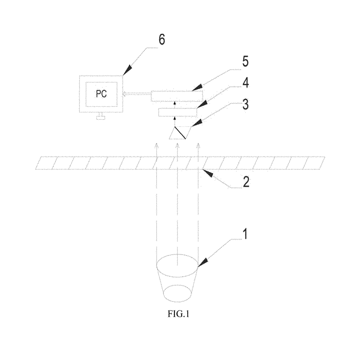
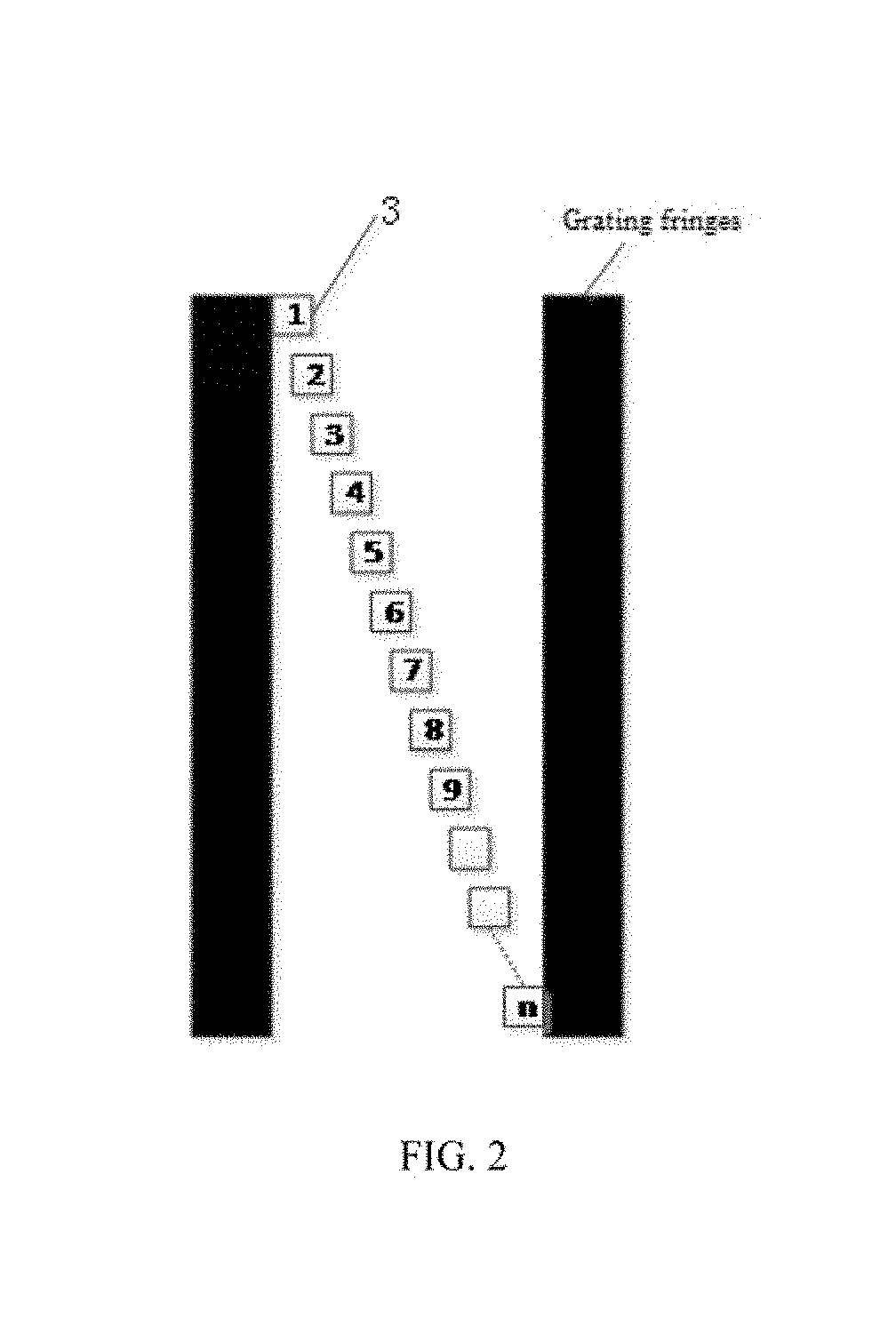
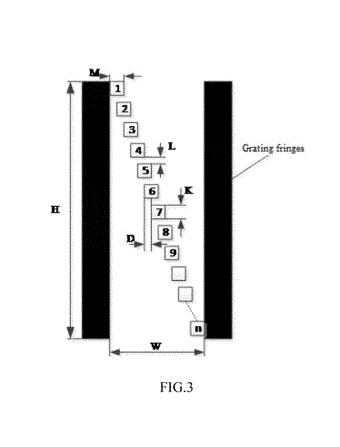
[0043]Referring to FIGS. 1 to 3, a novel array photoelectric sensor grating displacement detection system of the present embodiment includes a parallel light source 1, an incremental glass grating ruler 2, photoelectric sensor arrays 3, a high-speed voltage comparator 4, a signal processing unit 5 and a displacement display unit 6, wherein the incremental glass grating ruler 2 is perpendicular to an irradiation direction of the parallel light source 1; the photoelectric sensor arrays 3 are placed in a pitch of the incremental glass grating ruler 2 and separated from the grating ruler for a certain space, can be fixed to a bracket of a detected object and are uniformly distributed in a step shape; a vertical distance L between adjacent photoelectric sensors is equal to (grating height H−the number n of the photoelectric sensors*height K of the photoelectric sensors) / (the number n of the p...


PUM


Abstract

The present invention has the advantages of simple structure, low detection cost, high measurement precision, high detection speed, strong practicability, etc. The present invention relates to a novel array photoelectric sensor grating displacement detection system and method. The system includes a parallel light source, an incremental glass grating ruler, photoelectric sensor arrays, a high-speed voltage comparator, a signal processing unit and a displacement display unit, wherein the incremental glass grating ruler is perpendicular to an irradiation direction, of the parallel light source.

Description

CROSS-REFERENCE TO RELATED APPLICATIONS[0001]This application claims priority to Chinese Patent Application No. 201710772040.1 with a filing date of Aug. 31, 2017. The content of the aforementioned applications, including any intervening amendments thereto, are incorporated herein by reference.TECHNICAL FIELD[0002]The present invention relates to the technical field of precision measurement, in particular to a novel array photoelectric sensor grating displacement detection system and method.BACKGROUND OF THE PRESENT INVENTION[0003]In the field of precision measurement, a grating ruler is often used as a displacement feedback apparatus, and the grating ruler utilizes a grating optical principle to measure a displacement or an angle precisely.[0004]The existing grating ruler mainly includes two types, i.e., an incremental grating ruler and an absolute grating ruler, wherein the incremental grating ruler intervenes with an indicator grating through transmission or reflection depending ...

Claims


Application Information

Patent Timeline
IPC IPC(8): G01D5/347G01B11/02G01D5/26
CPCG01D5/26G01B11/026G01B11/02G01D5/34715G01D5/38
Inventor YANG, ZHIJUNLI, YANFENGCAI, TIEGENLI, QIANCHEN, XIN
Owner GUANGDONG UNIV OF TECH
Why Eureka
Try Eureka