
Rotation angle detection device and rotation angle detection method

a detection device and detection method technology, applied in measurement devices, dynamo-electric machines, instruments, etc., can solve problems such as easy effects on resolvers, and achieve the effects of suppressing the amount of heat generated by resolvers and excitation circuits, and improving resolver detection accuracy

Active Publication Date: 2018-12-11
MITSUBISHI ELECTRIC CORP
View PDF5 Cites 0 Cited by
  • Summary
  • Abstract
  • Description
  • Claims
  • Application Information

AI Technical Summary

Benefits of technology

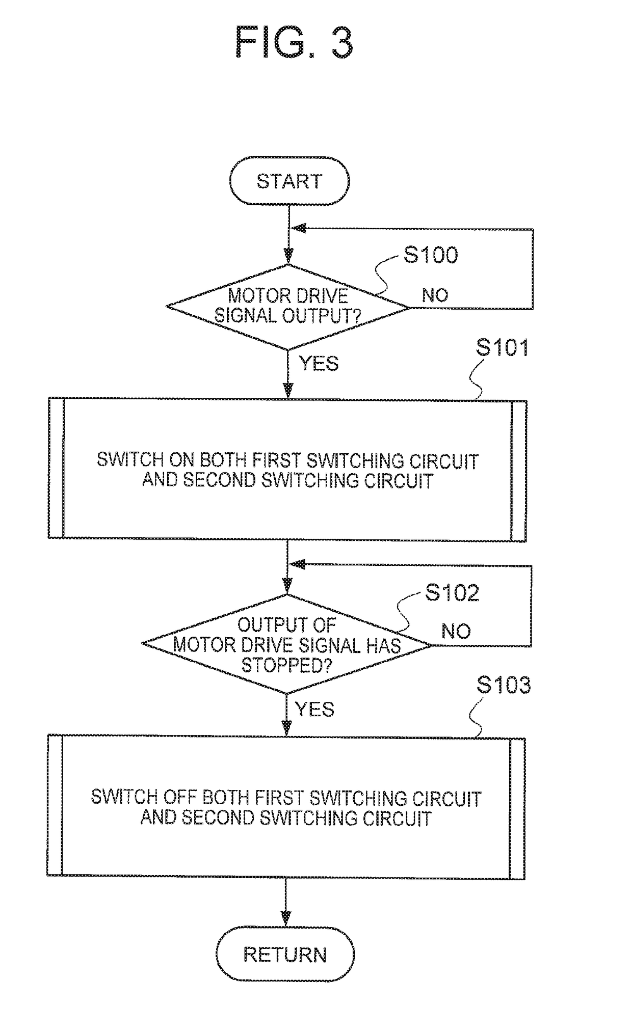
[0012]In the present invention, when the motor generator is performing a driving operation, the resolver detection accuracy is improved by raising the amplitude or frequency of the excitation signal. Furthermore, when a driving operation of the motor generator is not being performed, the amount of heat generated by the resolver and the excitation circuit is suppressed by reducing the amplitude or frequency of the excitation signal. As a result of this, it is possible to obtain a rotation angle detection device and a rotation angle detection method wherein downsizing can be achieved, and wherein a high resolver detection accuracy can be obtained during a driving operation of the motor generator, and when a driving operation of the motor generator is not being performed, the power consumption and amount of heat generated by the excitation circuit and resolver can be suppressed, while maintaining a resolver detection accuracy that enables information about the rotation speed of the motor generator to be obtained.

Problems solved by technology

However, resolvers are susceptible to the effects of external magnetic flux generated by the motor coil, etc. of the motor generator.

Method used


Image

  • Rotation angle detection device and rotation angle detection method
  • Rotation angle detection device and rotation angle detection method
  • Rotation angle detection device and rotation angle detection method

Examples


first embodiment

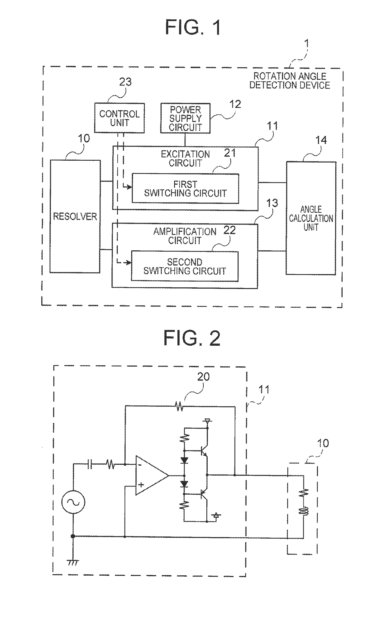
[0019]FIG. 1 is a block drawing showing the configuration of a rotation angle detection device 1 according to a first embodiment of the present invention. The rotation angle detection device 1 of the first embodiment comprises a resolver 10, an excitation circuit 11, a power supply circuit 12, an amplification circuit 13, an angle calculation unit 14, a first switching circuit 21, a second switching circuit 22, and a control unit 23.

[0020]Furthermore, FIG. 2 is a circuit diagram illustrating one example of the excitation circuit 11 in the rotation angle detection device 1 according to the first embodiment of the present invention. Below, the constituent elements and functions of the rotation angle detection device 1 according to the first embodiment will be described with reference to FIG. 1 and FIG. 2.

[0021]The resolver 10 has an excitation coil and an induction coil. A magnetic field produced by an excitation signal applied to the excitation coil of the resolver 10 is frequency-mo...

second embodiment

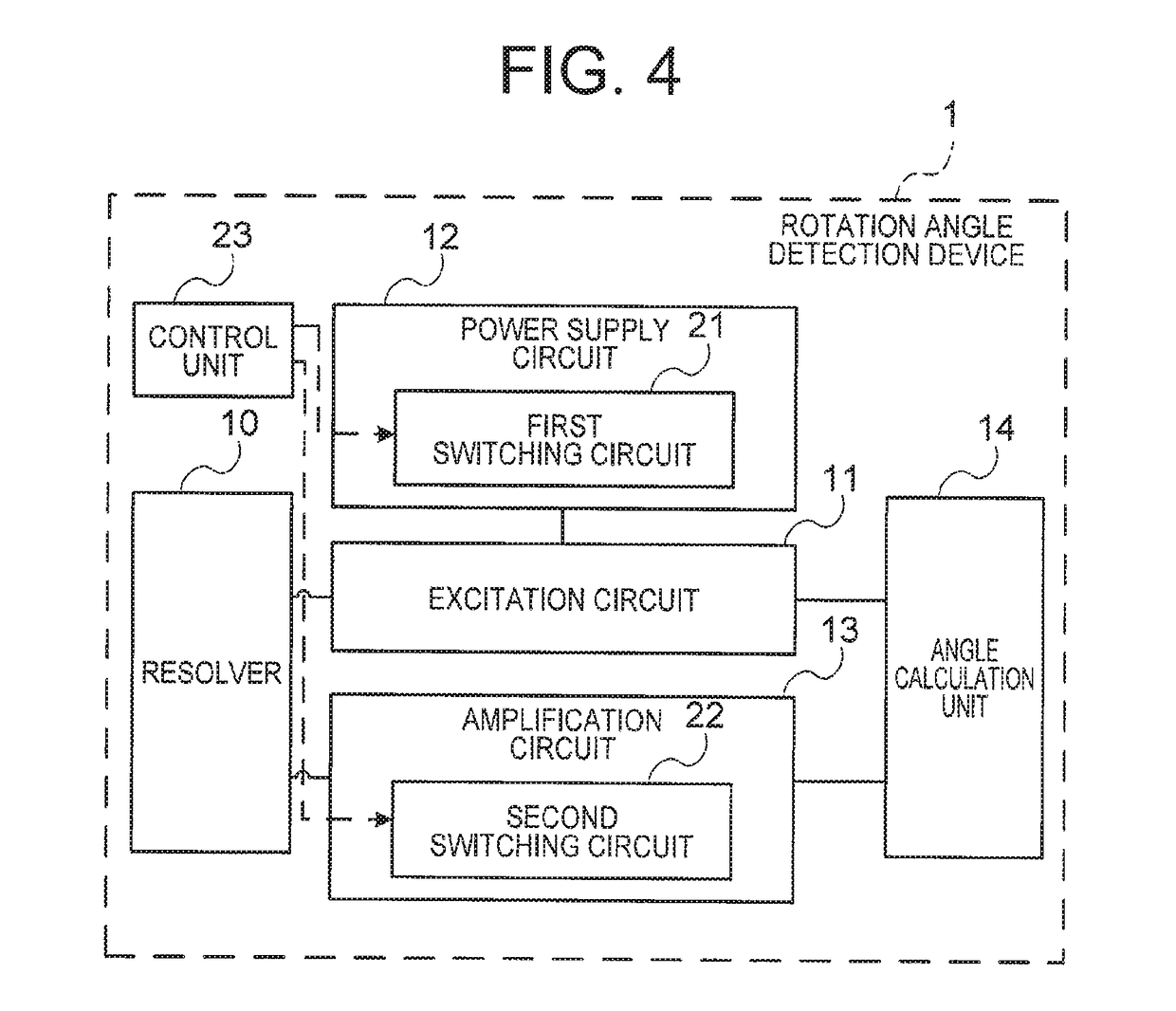
[0043]The first embodiment above describes a method which increases the amplitude of the excitation signal to improve the detection accuracy of the resolver 10 by providing the first switching circuit 21 in the excitation circuit 11 and switching the feedback resistance 20 of the operating amplifier of the excitation circuit 11. Meanwhile, the second embodiment describes a method in which the amplitude of the excitation signal is raised in accordance with the output voltage of the power supply circuit 12 to improve the detection accuracy of the resolver 10, by providing the first switching circuit 21 in the power supply circuit 12 and switching the output voltage of the power supply circuit 12.

[0044]FIG. 4 is a block drawing showing the configuration of the rotation angle detection device 1 according to the second embodiment of the present invention. FIG. 4 differs from FIG. 1 relating to the first embodiment in that the first switching circuit 21 is provided inside the power supply...

third embodiment

[0053]The first embodiment above describes a method which raises the amplitude of the excitation signal to improve the detection accuracy of the resolver 10 by switching the feedback resistance 20 of the operating amplifier of the excitation circuit 11. Meanwhile, a third embodiment of the present invention describes a method which raises the frequency of the excitation signal to improve the detection accuracy of the resolver 10, by switching the resistance of the excitation circuit 11 which sets the transmission frequency of the excitation signal.

[0054]A block diagram illustrating the configuration of the rotation angle detection device 1 according to the third embodiment of the present invention is the same as FIG. 1 relating to the first embodiment described above. However, the third embodiment differs from the first embodiment described above in that the first switching circuit 21 switches the frequency of the excitation signal, rather than the size of the excitation signal. The...


PUM


Abstract

In a rotation angle detection device for detecting a rotation angle and a rotation speed of a motor generator by using a resolver, a resolver detection accuracy is improved by raising the amplitude or frequency of an excitation signal when the motor generator is performing a driving operation. Furthermore, by reducing the amplitude or frequency of the excitation signal when the motor generator is not performing a driving operation, it is possible to suppress the amount of heat generated by the excitation circuit and the resolver, while maintaining a resolver detection accuracy that enables information about the rotation speed of the motor generator to be obtained.

Description

CROSS REFERENCE TO RELATED APPLICATIONS[0001]This application is a National Stage of International Application No. PCT / JP2014 / 079403 filed Nov. 6, 2014, the contents of all of which are incorporated herein by reference in their entirety.TECHNICAL FIELD[0002]The present invention relates to a rotation angle detection device and a rotation angle detection method for detecting a rotation angle and rotation speed of a motor generator, by using a resolver.BACKGROUND ART[0003]Resolvers, which have a simpler structure than optical encoders and show little error with temperature change, are widely used as rotation angle detection devices for detecting the rotation angle and rotation speed of a motor generator. However, resolvers are susceptible to the effects of external magnetic flux generated by the motor coil, etc. of the motor generator. Therefore, in order to reduce the effects of external magnetic flux, various structural measures have been devised for the coils of a resolver (see, fo...

Claims


Application Information

Patent Timeline
Patent Type & Authority Patents(United States)
IPC IPC(8): G01D5/20H02K24/00
CPCG01D5/20H02K24/00G01D5/2066
Inventor FUJIE, KENICHITSUJIMOTO, KATSUYATOTTORI, ISAOSUETAKE, NARUKI
Owner MITSUBISHI ELECTRIC CORP
Learn More