Rotor production method

a rotor and motor technology, applied in the direction of stator/rotor body manufacturing, magnetic materials, magnetic bodies, etc., can solve the problems of low motor efficiency and torque performance, cumbersome production method, and large complexity of permanent magnet production, so as to reduce eddy current loss and efficiently produce.

Active Publication Date: 2018-12-18
TOYOTA JIDOSHA KK
View PDF15 Cites 0 Cited by
  • Summary
  • Abstract
  • Description
  • Claims
  • Application Information

AI Technical Summary

Benefits of technology

[0013]The invention provides a rotor production method of efficiently producing a rotor including rare-earth magnets configured to reduce an eddy-current loss.
[0017]Because the insulating lubricant is applied to the interfaces of the sintered bodies adjacent to each other before hot working, the insulating lubricant is also present on interfaces of the split magnets adjacent to each other, which are formed by hot working. Thus, a rare-earth magnet in which insulation between the split magnets is ensured and which provides a good eddy-current loss reducing effect is produced.
[0029]As can be understood from the above description, with the rotor production method according to the aspect of the invention, the integrated magnet in which the split magnets are integrated with each other via the insulating lubricant on the interfaces thereof is produced in one molding die, and the rotor is produced by inserting the integrated magnet, as it is, into the magnet slot of the rotor. Thus, the rotor including the rare-earth magnet configured to reduce an eddy-current loss is efficiently produced.

Problems solved by technology

These losses lower the motor efficiency and the torque performance.
However, this production method requires many production steps, such as the step of performing an insulation coating process on the entirety of all the surfaces of each of the magnet pieces, and the step of joining together the magnet pieces that have undergone the insulation coating process.
This makes the production of a permanent magnet considerably cumbersome and complicated.
Further, an integrated magnet constituted by a plurality of magnet pieces produced individually as described above may fail to be accurately inserted into and installed in a magnet slot of a rotor, if the dimensional accuracy of each of the magnet pieces is not rigorously controlled.
Thus, these production methods may require a lot of time and effort.

Method used


Image

  • Rotor production method
  • Rotor production method
  • Rotor production method

Examples


Embodiment Construction

[0037]Hereinafter, a rotor production method according to an embodiment of the invention will be described with reference to the accompanying drawings. An integrated magnet illustrated in the drawings is formed by subjecting two sintered bodies to hot working. Alternatively, three or more sintered bodies may constitute an integrated magnet. In a rotor illustrated in the drawing, one integrated magnet forms one magnetic pole. Alternatively, two integrated magnets in a generally V-shape may form one magnetic pole.

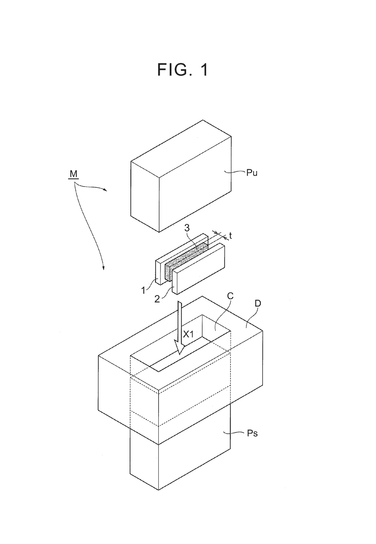
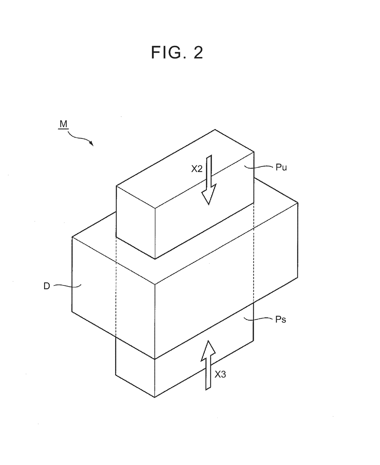
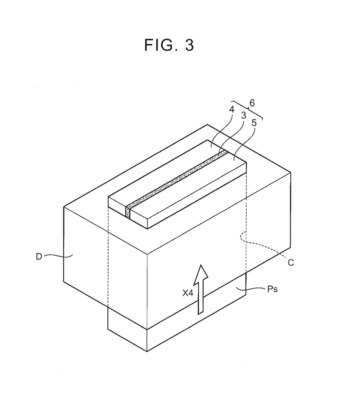
[0038]The rotor production method according to the embodiment will be described below. FIG. 1 is a perspective view illustrating a first step of the rotor production method according to the embodiment. FIGS. 2 and 3 are perspective views sequentially illustrating a second step of the rotor production method. FIG. 4 is a perspective view illustrating a third step of the rotor production method.

[0039]First, a molding die M is provided. As illustrated in FIG. 1, the molding die ...


PUM

PropertyMeasurementUnit
thicknessaaaaaaaaaa
temperatureaaaaaaaaaa

Abstract

A rotor production method includes: a first step of arranging a plurality of sintered bodies side by side with an insulating lubricant applied to an interface of at least one of the sintered bodies adjacent to each other, and then housing the sintered bodies in a cavity of a molding die such that the sintered bodies are arranged side by side in the cavity, the sintered bodies being precursors of a plurality of split magnets constituting one rare-earth magnet; a second step of turning the sintered bodies into the split magnets by performing hot working to impart magnetic anisotropy to the sintered bodies arranged in the cavity, and producing an integrated magnet in which the split magnets are integrated together with the lubricant interposed therebetween; and a third step of producing a rotor of a motor by inserting the integrated magnet into a magnet slot of the rotor.

Description

INCORPORATION BY REFERENCE[0001]The disclosure of Japanese Patent Application No. 2015-137282 filed on Jul. 8, 2015 including the specification, drawings and abstract is incorporated herein by reference in its entirety.BACKGROUND OF THE INVENTION[0002]1. Field of the Invention[0003]The invention relates to a method of producing a rotor of a motor.[0004]2. Description of Related Art[0005]In the automobile industry, development of higher-powered, lighter and more compact driving motors has been constantly advanced for the purpose of further improving travelling performance of hybrid vehicles and electric vehicles. Similarly, household electric appliance manufacturers have focused on development of more compact and higher-powered motors incorporated in various kinds of household electric appliances.[0006]How to reduce various kinds of losses caused inside motors is an important issue to be addressed in order to improve performance of the motors. For example, after application of electr...

Claims


Application Information

Patent Timeline
Patent Type & Authority Patents(United States)
IPC IPC(8): H02K15/03H01F1/057H01F41/02
CPCH02K15/03H01F1/0576H01F1/0577H01F41/0273H01F41/0253Y10T29/49078Y10T29/49076
Inventor YAMASHITA, OSAMU
Owner TOYOTA JIDOSHA KK
Why Eureka
Try Eureka