Active vibration controller

a technology of active vibration and controller, which is applied in the direction of magnetic springs, low internal friction springs, mechanical apparatus, etc., can solve the problems of insufficient damping effect, inability to fully give the damping effect of the dynamic absorber, and the difficulty of directly applying outer energy, so as to improve increase the variation in the stiffness of the magnetic viscoelastic elastomer, and reduce the limit of the bas

Active Publication Date: 2018-12-25
HONDA MOTOR CO LTD
View PDF13 Cites 7 Cited by
  • Summary
  • Abstract
  • Description
  • Claims
  • Application Information

AI Technical Summary

Benefits of technology

[0006]On the other hand, as a counter part of the passive type of damping device, an active mass damper is known. In this method, an actuator for forcibly vibrating a mass is installed in addition to the mass element. This provides a high damping effect irrespective of stable or unstable in frequency because, theoretically, an arbitrary damping force can be generated though any disturbance is applied. However, there are problems in that a device to directly apply outer energy becomes complicated and that a control system designing become necessary to avoid unstableness, and that a cost is high. Further, there is a semi-active type of a control method which is an intermediate type between the passive type and the active type. In the semi-active type of damper, a physical characteristic of one of configuration elements, which is originally fixed in the passive type system, is made variable with some means to have variability in the physical characteristic in the system. This enables the system control while the variation due to a disturbance is tracked to some extent. The semi-active type of control method has advantageous effects such as a control performance close to the active type of control method with reliability and stability derived from the passive elements and provides a device at a cost which is lower than that of the active type of control.
[0007]WO 2012 / 026332 discloses a configuration for varying an elastic modulus of a magnetic elastic body by application of a magnetic field generated by an exciting coil using a configuration in which the exciting coil is arranged around an outer circumference of a magnetic elastic body of which elastic modulus can be changed by application of a magnetic field by the exciting coil.
[0008]WO 2012 / 026332 disclosed a technology in which a stiffness of a magnetic viscoelastic elastomer is changed by application of a magnetic field to the magnetic response-type elastic body (magnetic viscoelastic elastomer) is changed. When the magnetic field is applied to the magnetic viscoelastic elastomer, the magnetic field is applied to the magnetic viscoelastic elastomer uniformly and varies the stiffness of the magnetic viscoelastic elastomer in accordance with the application intensity of the magnetic field. The magnetic viscoelastic elastomer can be produced by dispersing magnetic particles in, for example, rubber.
[0009]However, it was forced to distribute the magnetic particles in a part which does not largely contribute to change the stiffness of the magnetic viscoelastic elastomer, it is necessary to increase an amount of the magnetic particles included in a base material to increase a variation in stiffness of the magnetic viscoelastic elastomer. This may invite an increase in a lower limit of the base stiffness of the magnetic viscoelastic elastomer.
[0010]Further, the magnetic field cannot be applied to the magnetic viscoelastic elastomer efficiently because the magnetic field may be applied to the part of the magnetic viscoelastic elastomer in which the magnetic particles are not distributed, so that it was not performed to apply the magnetic field to the magnetic viscoelastic elastomer efficiently. Accordingly, it was forced to increase a magnitude of the generated magnetic filed by increasing the applied current to generate the magnetic field. In addition, there is a problem in that an effect of the magnetic viscoelastic elastomer as a spring in a dynamic damper may be low because the magnetic viscoelastic elastomer has a large attenuation characteristic.SUMMARY OF THE INVENTION
[0011]An aspect of the present invention provides an active vibration controller capable of efficiently apply the magnetic field to the magnetic viscoelastic elastomer with a manufacturing cost of the magnetic viscoelastic elastomer being decreased.

Problems solved by technology

However, when the frequency of the disturbance vibration is different from the eigenfrequency even slightly or when the frequency of the disturbance vibration varies as time passes, i.e., in an unstable state, the damper effect of the dynamic absorber cannot be fully given.
However, its damping effect is insufficient.
However, there are problems in that a device to directly apply outer energy becomes complicated and that a control system designing become necessary to avoid unstableness, and that a cost is high.
Further, the magnetic field cannot be applied to the magnetic viscoelastic elastomer efficiently because the magnetic field may be applied to the part of the magnetic viscoelastic elastomer in which the magnetic particles are not distributed, so that it was not performed to apply the magnetic field to the magnetic viscoelastic elastomer efficiently.
In addition, there is a problem in that an effect of the magnetic viscoelastic elastomer as a spring in a dynamic damper may be low because the magnetic viscoelastic elastomer has a large attenuation characteristic.

Method used


Image

  • Active vibration controller
  • Active vibration controller
  • Active vibration controller

Examples


first embodiment

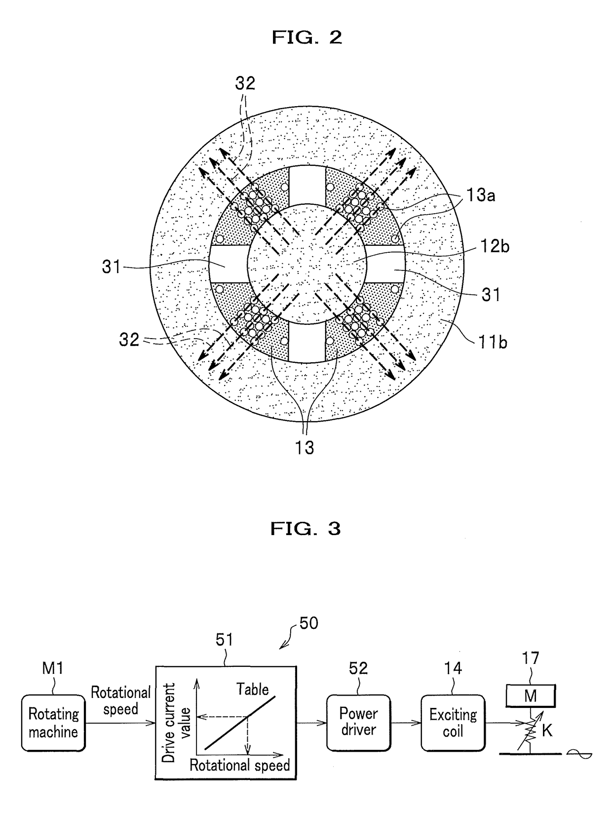
[0036]A first embodiment of the present invention is described below in detail, referring to the attached drawing.

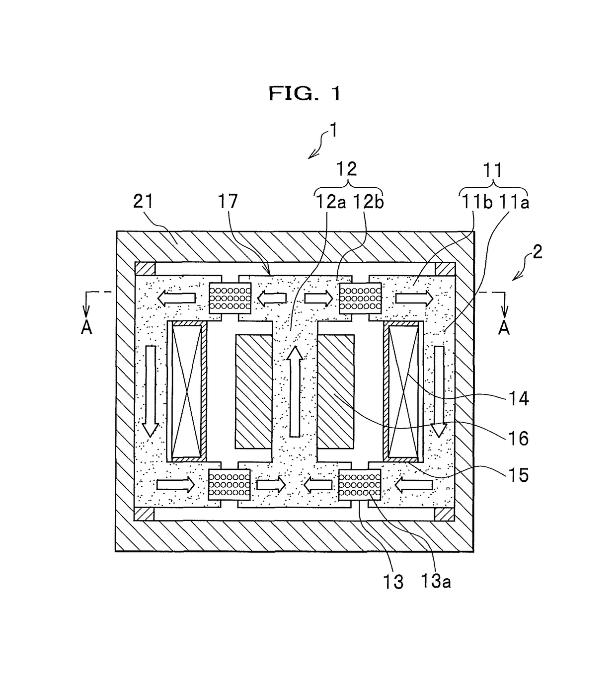
[0037]FIG. 1 is an elevational sectional view of the active vibration controller according to the first embodiment of the present invention.

[0038]An active vibration controller 1 includes a housing 21 having a non-magnetic hollow circular cylinder. The housing 21 houses therein a movable part 17 which can move in response to vibrations from the outside and a first magnetic core 11. The movable part 17 includes a second magnetic core 12 and an adjusting mass 16. Further, the housing 21 houses an exciting coil 14 for generating a magnetic field having intensity according to the current supplied thereto. The exciting coil 14 is made by winding a wire around a bobbin 15 having an annular shape.

[0039]The first magnetic core (first magnetic member) 11 and the second magnetic core (second magnetic member) 12 are a plurality of (two in this example) magnetic members forming a cl...

second embodiment

[0055]The below embodiments have the same general configurations as that of the first embodiment as shown in FIGS. 1 and 3, and thus, a detailed illustration and description are omitted.

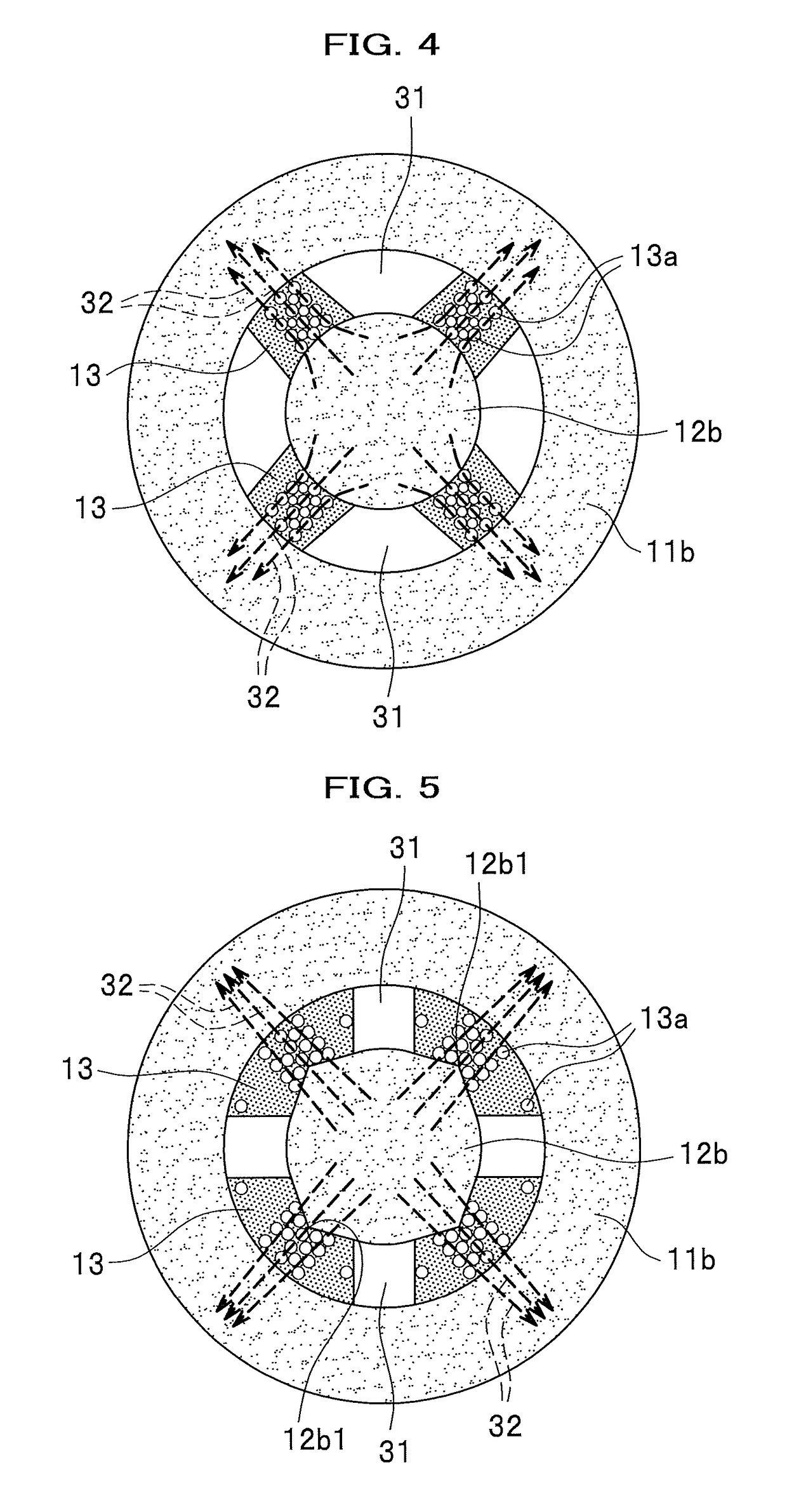
[0056]The difference between the first embodiment and the second embodiment is in that a configuration shown in FIG. 4 is used in place of the configuration shown in FIG. 2.

[0057]More specifically, the magnetic viscoelastic elastomer 13 is formed to have a cross sectional area orthogonal with a direction (opposite direction) of the magnetic flux lines 32 transmitting through the magnetic viscoelastic elastomer 13 is made smaller in the direction (opposite direction) as the cross sectional area go closer to the first magnetic core 11 (second magnetic core).

[0058]This makes the magnetic flux lines 32 concentrated, which can apply the magnetic field to the magnetic viscoelastic elastomer 13 efficiently.

third embodiment

[0059]There is a difference between the first embodiment and the third embodiment is a configuration shown in FIG. 5 is used in place of the configuration shown in FIG. 2. More specifically, the second magnetic core 12b has protruding portions 12b1 each protruding from a connection place thereof with the magnetic viscoelastic elastomer 13 toward the magnetic viscoelastic elastomer 13.

[0060]This makes the magnetic flux lines 32 concentrated at the protruding portion 12b1, so that the magnetic field can be applied to the magnetic viscoelastic elastomer 13 efficiently.


PUM

PropertyMeasurementUnit
toric shapeaaaaaaaaaa
magnetic fieldaaaaaaaaaa
magnetic viscoelastic propertyaaaaaaaaaa

Abstract

An active vibration controller includes: a housing; a first magnetic member installed on the side of the housing having a toric shape; a movable member including a second magnetic member that is substantially coaxial with the first magnetic member and disposed inside the toric shape of the first magnetic member; an exciting coil that generates a magnetic field in accordance with an intensity of a current supplied thereto; and a magnetic viscoelastic elastomer that has a magnetic viscoelastic property varying in accordance with a magnitude of the magnetic field from the exciting coil between the first and second tip portions, and connects the first magnetic core to the second magnetic core. The magnetic viscoelastic elastomer has a region having a non-magnetic property between the first and the second magnetic cores.

Description

CROSS REFERENCE TO RELATED APPLICATION[0001]This application claims the foreign priority benefit under Title 35, United States Code, § 119(a)-(d) of Japanese Patent Application No. 2016-095319, filed on May 11, 2016 in the Japan Patent Office, the disclosure of which is herein incorporated by reference in its entirety.BACKGROUND OF THE INVENTION[0002]1. Field of the Invention[0003]The present invention relates to an active vibration controller.[0004]2. Description of the Related Art[0005]In conventional passive-type vibration absorbers, an eigenvalue of the vibration absorber is uniquely determined because a physical property of the configuration elements is fixed. Accordingly, when a frequency of the disturbance vibration agrees with the eigenfrequency of the vibration absorber, a high damper effect is given. However, when the frequency of the disturbance vibration is different from the eigenfrequency even slightly or when the frequency of the disturbance vibration varies as time p...

Claims


Application Information

Patent Timeline
Patent Type & Authority Patents(United States)
IPC IPC(8): F16F1/36F16F15/03F16F6/00
CPCF16F1/3615F16F15/03F16F1/361F16F6/00
Inventor TERASHIMA, OSAMUINOUE, TOSHIO
Owner HONDA MOTOR CO LTD
Why Eureka
Try Eureka