Check patentability & draft patents in minutes with Patsnap Eureka AI!

Double-sided card edge connector

a technology of edge connectors and cards, applied in the direction of coupling contact members, coupling device connections, securing/insulating coupling contact members, etc., can solve the problems of increasing the number of kinds of necessary components, increasing and requiring extra time and effort for parts management, so as to increase the number and increase the risk of assembly errors

Active Publication Date: 2018-12-25
NIPPON TANSHI CO LTD +2
View PDF5 Cites 0 Cited by
  • Summary
  • Abstract
  • Description
  • Claims
  • Application Information

AI Technical Summary

Benefits of technology

The present invention aims to provide a connector with mutually facing terminal members that have contacting portions offset in the insertion direction without increasing the number of components required for offset arrangement and without increasing the risk of assembly error. This will save time and effort for parts management.

Problems solved by technology

This increases the number of kinds of necessary components, increases the risk of assembly error, and also requires extra time and effort for parts management.

Method used


Image

  • Double-sided card edge connector
  • Double-sided card edge connector
  • Double-sided card edge connector

Examples


Embodiment Construction

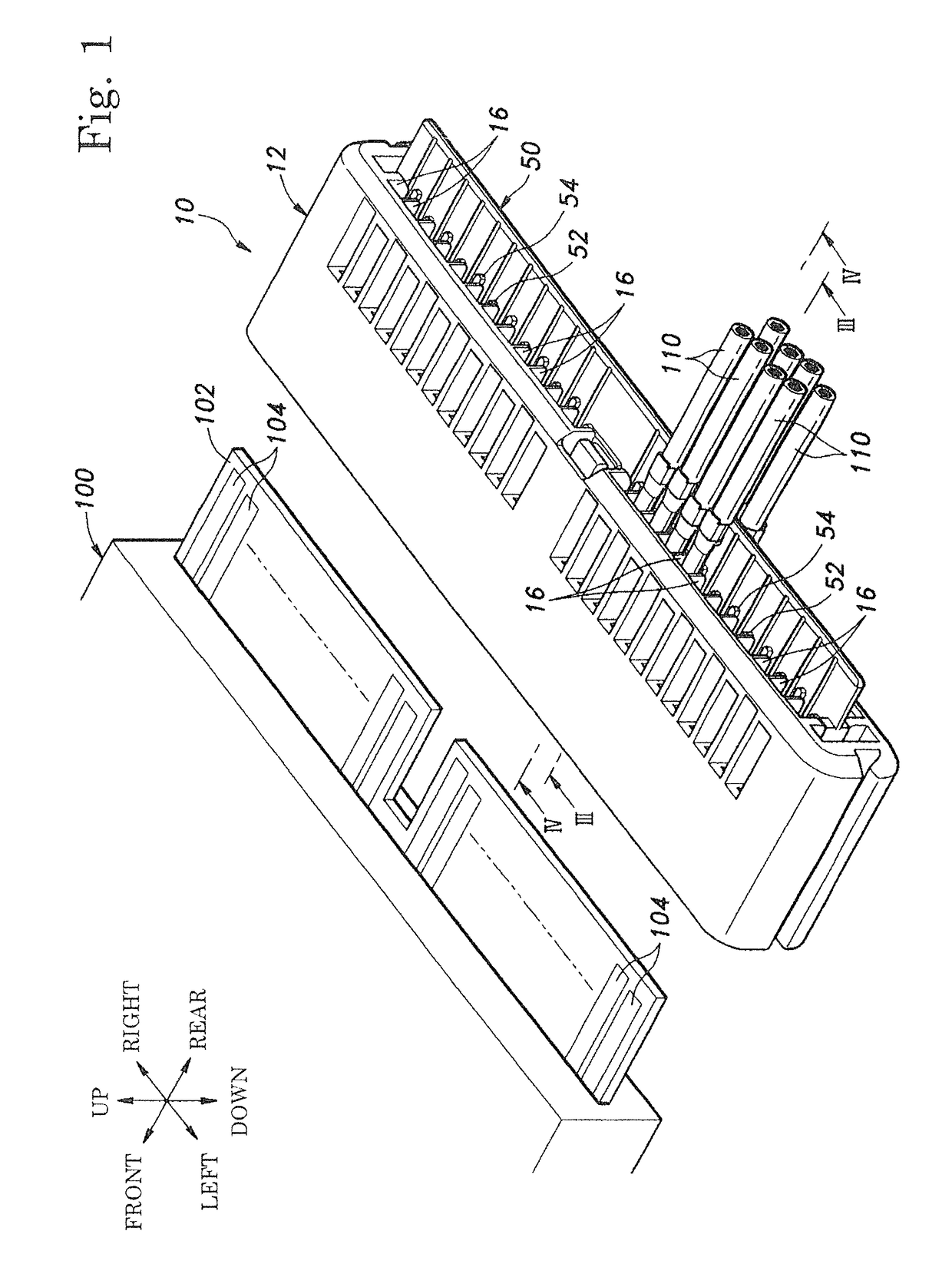
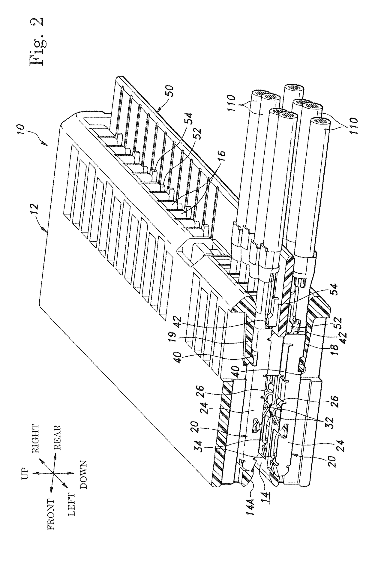
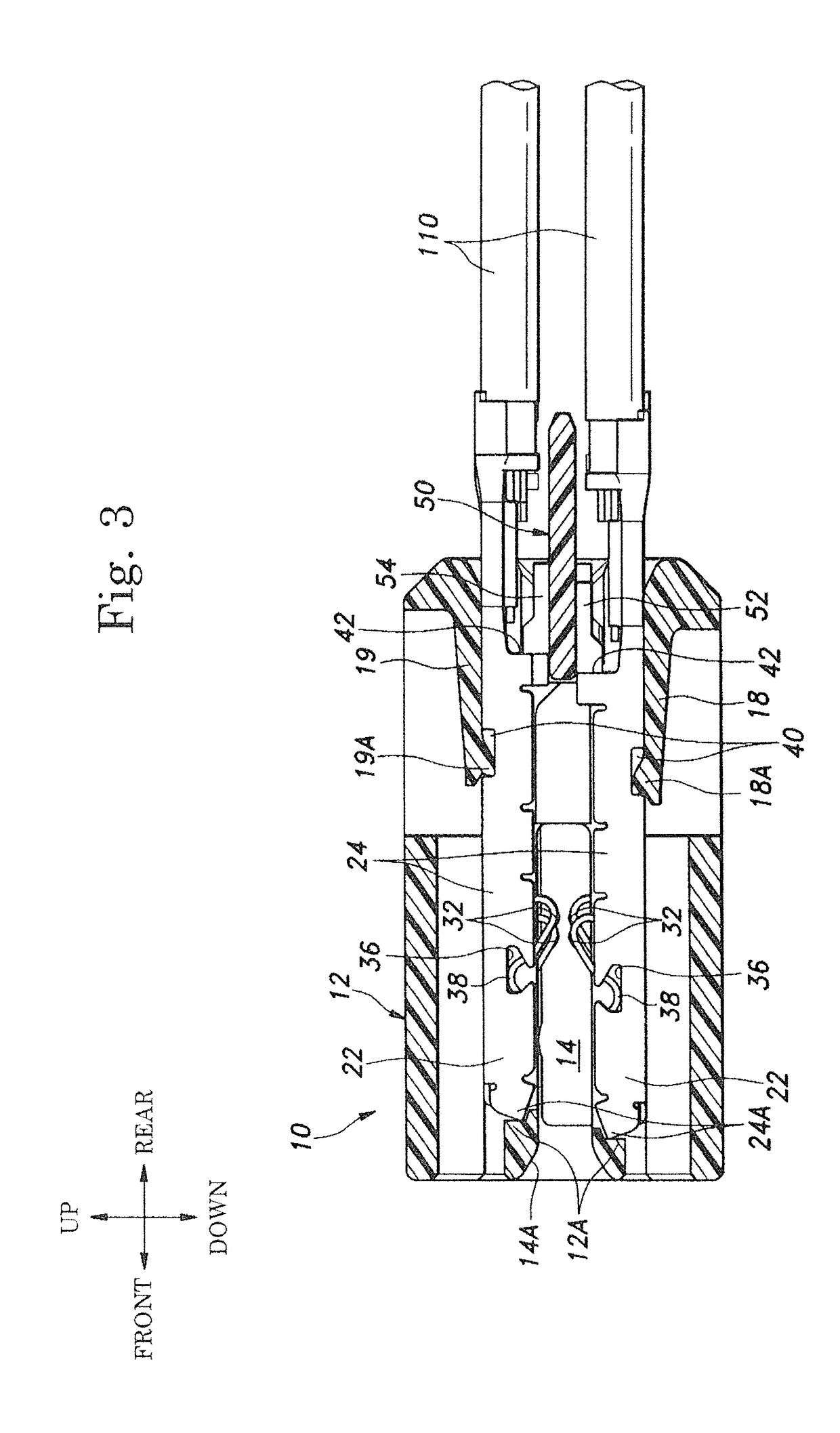
[0042]An embodiment of a double-side card edge connector in accordance with the present invention will now be described with reference to FIG. 1 to FIG. 7.

[0043]The double-sided card edge connector in accordance with the embodiment is overall designated by reference numeral 10. The double-sided card edge connector 10 is a connector for electric connection for a double-sided card edge 102. As illustrated in FIG. 1, the double-sided card edge 102 protrudes outward from an outer case 100 of electrical equipment such as a microcomputer and the like, and has a plurality of layer board terminals 104 formed on each of its top-surface and undersurface (not shown) as part of a double-sided print board, the board terminals 104 being arranged to be positioned at equal pitch in the left-right direction. In the embodiment, the 24 board terminals 104 are formed on each of the top-surface and undersurface of the double-sided card edge 102. Adjacent board terminals 104 of the board terminals 104 di...


PUM


Abstract

To prevent an increase of the number of kinds of components required for offset arrangement, an increase in risk of assembly error and extra time and effort for parts management, in a connector including mutually facing terminal members with contacting portions being offset in the insertion direction. Mutually facing terminal members 20 are formed on components identical in shape. The mutually facing terminal members 20 are secured to a connector housing 12 while being offset in an insertion direction of a double-sided card edge 102 inserted into a receptacle compartment 14 of the connector housing 12.

Description

BACKGROUND OF THE INVENTION1. Field of the Invention[0001]This invention relates to a double-sided card edge connector.2. Description of the Related Art[0002]A double-sided card edge connector (hereinafter abbreviated as a “connector”) is known which has a connector housing including a receptacle compartment into which a card edge of a double-sided print board is inserted, and a terminal member including contact pieces having spring characteristics, the terminal member being attached to the connector housing such that the contact pieces are located on both sides of the receptacle compartment to face each other. The contact pieces include contacting portions coming into contact with the card edge located in a position inserted into the receptacle compartment, the mutually facing contacting portions of the terminal member are offset in an insertion direction of the card edge being inserted into the receptacle compartment (for example, Patent Literature 1).[0003]In such a connector, be...

Claims


Application Information

Patent Timeline
Patent Type & Authority Patents(United States)
IPC IPC(8): H01R12/00H01R13/40H01R12/75H01R12/72H01R13/424
CPCH01R12/721H01R13/424H01R13/40H01R12/75H01R13/02H01R13/46
Inventor ENOMOTO, SHINYANISHIMURA, OSAMUFUJINO, MASARUOCHIAI, NOBUHIKOINOUE, YUYAIIJIMA, MAKOTOINOUE, KOICHIITO, YASUAKINISHIZAKI, HIROYOSHIARIMAI, FUMIAKI
Owner NIPPON TANSHI CO LTD
Features
  • R&D
  • Intellectual Property
  • Life Sciences
  • Materials
  • Tech Scout
  • Unparalleled Data Quality
  • Higher Quality Content
  • 60% Fewer Hallucinations
Learn More