
Milling machine and method for operating a milling machine

a milling machine and milling machine technology, applied in the field of milling machines, can solve the problem that the optimal parameters of the milling machine operation cannot be determined and established, and achieve the effect of simple setting of machine parameters

Active Publication Date: 2019-01-01
WIRTGEN GMBH
View PDF22 Cites 1 Cited by
  • Summary
  • Abstract
  • Description
  • Claims
  • Application Information

AI Technical Summary

Benefits of technology

[0016]An object of the invention is to furnish a milling machine that enables simple setting of machine parameters suitable for the milling task that is to be carried out. A further object of the invention is to furnish a milling drum suitable therefor, and a corresponding method.
[0020]The predefined value to be set, or the predefined setting range, makes it easier for an operator of the milling machine to select suitable machine parameters. Incorrect settings can be avoided. This has a positive effect on the quality of the working result obtained, on milling performance, on the energy consumption of the milling machine, and on the wear on the milling tools.
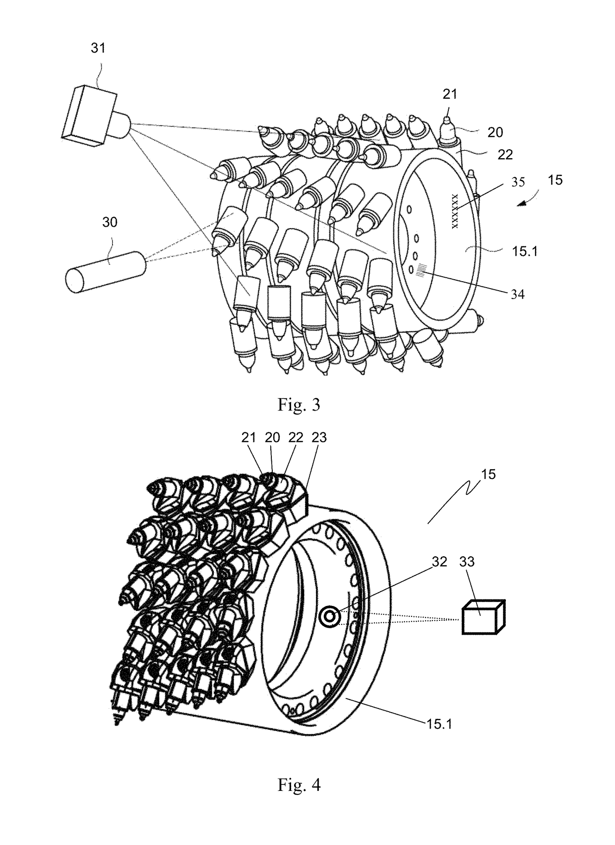
[0027]Provision can preferably be made that an identifying element, in particular a letter sequence and / or number sequence, and / or a barcode, is arranged in or on the milling drum as a characteristic feature. The milling drum is unequivocally described by the identifying element. It can be detected by way of respectively suitable means. For example, a barcode can be read out by means of a corresponding barcode reader provided on the milling machine. A letter sequence or number sequence used as an identifying element can represent a serial number of the milling drum. This can be read off by an operator of the milling machine and inputted via the input device. It is also possible for the letter sequence or number sequence to be detected with the aid of a suitable sensor or the camera. All the variants described enable rapid and unequivocal recognition of the type of milling drum installed in the milling machine, so that a value to be set, or a setting range, for the at least one machine parameter can be specified.
[0031]An identifying element, constituting a characteristic feature of the milling drum which unequivocally establishes the type of milling drum, can be permanently stored in such a transponder. A transponder of this kind can be read out in quick and error-free fashion even in harsh environmental conditions.
[0034]Suitable operation of the milling machine can be ensured in particular by the fact that the control unit is designed to specify, depending on the characteristic feature and / or on the type of milling drum determined from the characteristic feature, the value to be set, or the setting range, for a milling depth and / or a milling drum rotation speed and / or an advance speed of the milling machine and / or a drive power transferred to the milling drum and / or a torque transferred to the milling drum and / or a rotation speed of a motor driving the milling drum, as a machine parameter of the milling machine. The operation of the milling machine can be optimally adapted to the respective milling task, and to the milling drum being used, by setting these, or some of these, machine parameters. Provision can also be made that the control unit is designed to specify, depending on the characteristic feature and / or on the type of milling drum determined from the characteristic feature, a maximum milling depth and / or a minimum advance speed and / or a maximum advance speed. The setting range for the milling depth and the advance speed of the milling machine can thereby be unequivocally narrowed down and specified.
[0039]Provision can additionally be made that the control unit is designed to identify individual milling drums depending on the characteristic feature, and to detect the operating duration of the milling drum and / or replacement intervals for milling tools of the milling drum. The data thereby acquired can be used to optimize the load on the milling drum and to optimize replacement intervals for the milling tools, in particular bits, and thus to prevent damage to the milling drum. For this, provision can be made that additional information for operation of the milling drum (for example, points in time for bit changes, number of bits replaced, or the like) is detected by the control unit. This additional information can be inputted, for example, by the operator via existing input means of the control unit.

Problems solved by technology

Disadvantageously, it can happen in this context that the initial value of the variable operating parameter is specified in a range that is not suitable for the milling task at hand.
It is furthermore disadvantageous that with this method, the optimum parameters for operation of the milling machine can only be ascertained and established during the milling process.

Method used


Image

  • Milling machine and method for operating a milling machine
  • Milling machine and method for operating a milling machine
  • Milling machine and method for operating a milling machine

Examples


Embodiment Construction

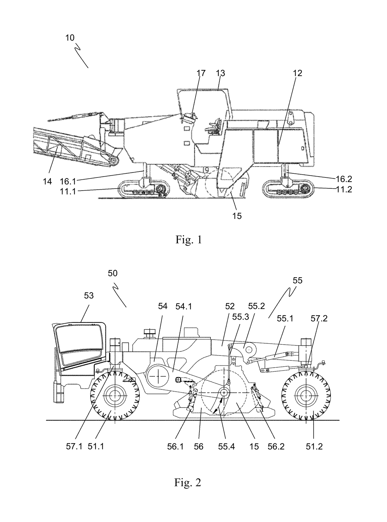
[0052]FIG. 1 is a schematic side view depicting a first milling machine 10 in the form of a road milling machine. A machine frame 12 is carried by drive units 11.1, 11.2, for example track drive units, vertically adjustably via four lifting columns 16.1, 16.2. First milling machine 10 can be operated from a control station 13 via a control system 17 arranged in control station 13. A milling drum 15, depicted with dashed lines in the Figure and arranged in concealed fashion, is rotatably mounted in a milling drum housing that is likewise arranged in concealed fashion. A conveyor device 14 serves to transport the milled material away.

[0053]In use, machine frame 12 is moved, at an advance speed inputted via control system 17, over the substrate to be worked, in which context bits 20, arranged in the rotating milling drum 15 and shown in FIGS. 3 and 4, remove the substrate. The vertical position and the rotation speed of milling drum 15 can be set from control system 17. The milling dep...


PUM


Abstract

The invention relates to a milling machine having a replaceable milling drum, different types of milling drums being capable of being associated with the milling machine; and having a control unit for controlling the milling machine, machine parameters of the milling machine being settable by way of the control unit. Provision is made that the milling machine has associated with it at least one means that is designed to detect at least one characteristic feature of the milling drum; that the at least one means is connected to the control unit; and that the control unit is designed to specify for at least one machine parameter, indirectly or directly from the characteristic feature, a value to be set, and / or a setting range. The invention further relates to a corresponding milling drum and to a corresponding method. The milling machine, milling drum, and method allow the selection of machine parameters for operation of the milling machine to be simplified.

Description

BACKGROUND OF THE INVENTION1. Field of the Invention[0001]The invention relates to a milling machine, in particular a road milling machine, a stabilizer, a recycler, a surface miner, or the like, having a replaceable milling drum, different types of milling drums being capable of being associated with the milling machine; and having a control unit for controlling the milling machine, machine parameters of the milling machine being settable by way of the control unit.[0002]The invention further relates to a milling drum for such a milling machine, and to a method for operating such a milling machine.2. Description of the Prior Art[0003]Ground milling machines are used for many different tasks, for example in road and street construction or for raw materials extraction by surface mining.[0004]In the context of road milling, for example, in one possible application it is known to process the surface of traffic routes by so-called “fine milling,” for example in order to improve the nons...

Claims


Application Information

Patent Timeline
Patent Type & Authority Patents(United States)
IPC IPC(8): E21C35/24E21C25/10E01C23/088E21C41/00E01C21/00
CPCE21C35/24E01C21/00E21C41/00E21C25/10E01C23/088E01C23/127
Inventor BERNING, CHRISTIANLEHNERT, THOMASVERHAELEN, PHILIP
Owner WIRTGEN GMBH
Learn More