
Vehicle seat

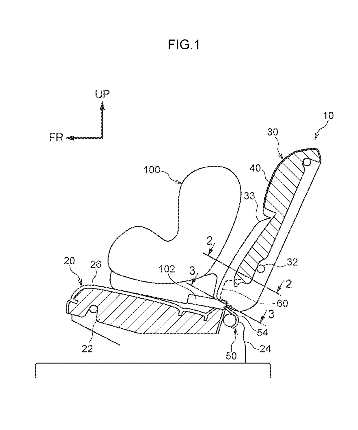
a seat and seat technology, applied in the field of seat seats, can solve the problem of inferior external appearance of the seatback, and achieve the effect of simplifying the shape facilitating the processing of the seatback pad

Inactive Publication Date: 2019-01-08
NHK SPRING CO LTD
View PDF19 Cites 0 Cited by
  • Summary
  • Abstract
  • Description
  • Claims
  • Application Information

AI Technical Summary

Benefits of technology

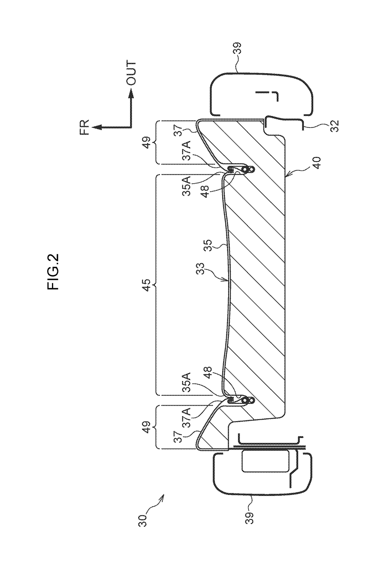
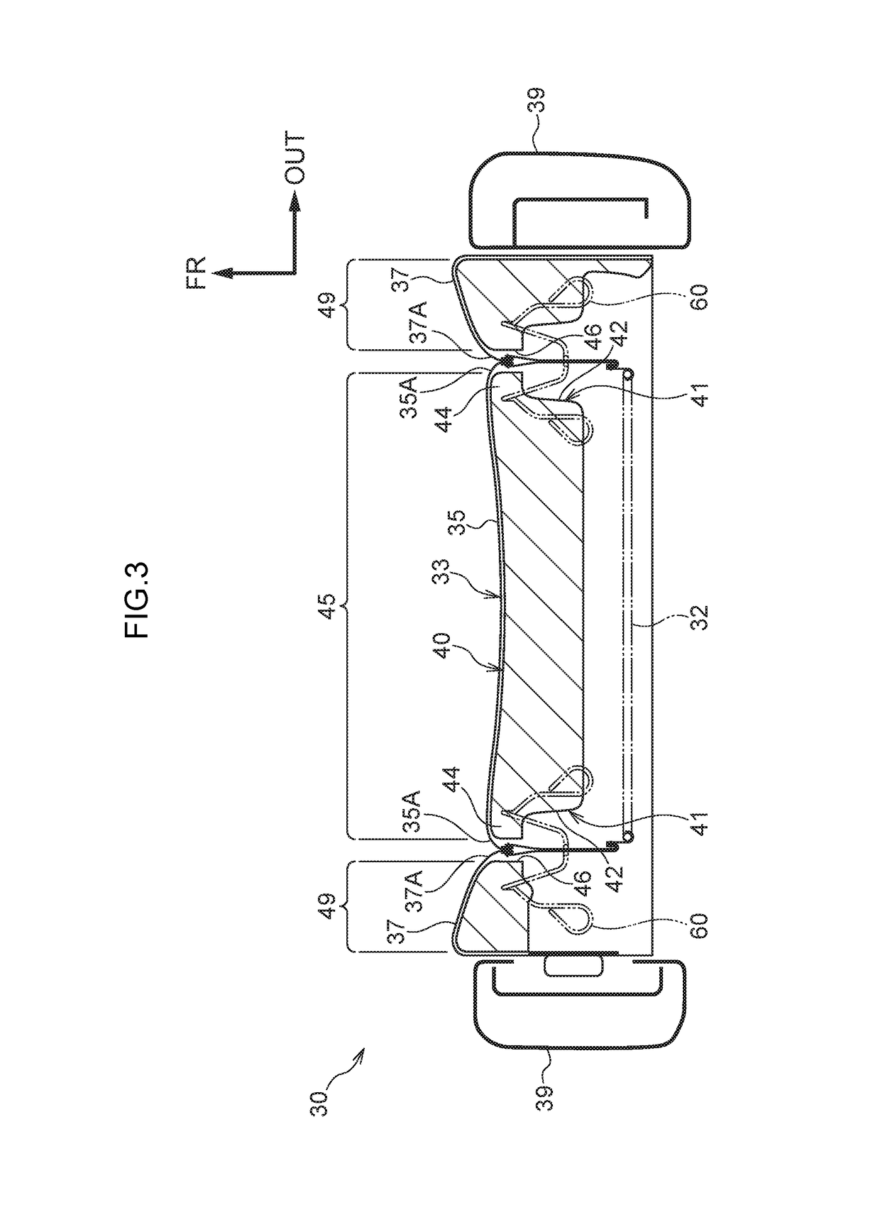
The patent describes a child seat with a seatback pad that has a connector for attaching a seat belt. The seatback pad has two coverings that are pulled together to close the opening where the connector is inserted. The coverings are reinforced to maintain their shape and prevent an inferior external appearance of the seatback. The seatback pad has a vertical groove that simplifies its shape and makes it easier to process. The technical effects of this invention are that it provides a child seat with a seatback pad that has a connector for attaching a seat belt while maintaining a good external appearance.

Problems solved by technology

However, when the slit openings are enlarged, load from repeated insertion of the connector or from an occupant is liable to cause wrinkling and the like in the covering, and there is concern of this causing the seatback to have an inferior external appearance.

Method used


Image

  • Vehicle seat
  • Vehicle seat
  • Vehicle seat

Examples


first modified example

[0099](First Modified Example of Pull-In Structure)

[0100]Explanation follows regarding a first modified example of a pull-in structure at the lower end portions of the edge 35A and the edge 37A. Note that explanation of portions that are the same as in the exemplary embodiment described above is omitted as appropriate.

[0101]As illustrated in FIG. 14, in the first modified example, the lower end portions of the edge 35A and the edge 37A (portions disposed in the slit 46) are stitched to respective front end portions (examples of other end portions) of a pull-in cloth 182 (an example of a first pull-in member) and a pull-in cloth 183 (an example of a second pull-in member). The lower end portions of the edge 35A and the edge 37A are not stitched together and so are capable of separating from each other.

[0102]A front end portion of the pull-in cloth 182 is disposed at a seat width direction inside with respect to a front end portion of the pull-in cloth 183, and a rear end portion (an ...

second modified example

[0107](Second Modified Example of Pull-In Structure)

[0108]Explanation follows regarding a second modified example of a pull-in structure at the lower end portions of the edge 35A and the edge 37A. Note that explanation of portions that are the same as in the exemplary embodiment described above is omitted as appropriate.

[0109]As illustrated in FIG. 17 and FIG. 18 (an enlarged view of FIG. 17), in the second modified example, resin plates 235, 237 (examples of reinforcement members) are disposed at the lower end portions of the edge 35A and the edge 37A (portions disposed in the slit 46).

[0110]In a state in which the resin plates 235, 237 are tucked inside the respective edges 35A, 37A, the resin plates 235, 237 are then sewn together with the front end portions (an example of other end portions) of the pull-in cloth 282 (an example of a first pull-in member) and the pull-in cloth 283 (an example of a second pull-in member), respectively. The lower end portions of the edge 35A and th...


PUM


Abstract

Lower end portions of an edge and another edge are fixed to a wire through pull-in cloths and a fixing member such that the pull-in cloths pull the lower end portions in toward the rear and into an opening (slit). This enables the edge and the another edge to be closed together in a state in which tension is applied to a front covering and a side covering. This enables the external appearance of a seatback to be preserved. Further, the edge and the another edge can be separated from each other, enabling a connector to be inserted into the opening from between the edge and the another edge, and the connector to be connected to an ISOFIX member. An inferior external appearance of the seatback can accordingly be suppressed while securing insertability of the connector.

Description

CROSS-REFERENCE TO RELATED APPLICATION[0001]This application claims priority under 35 USC 119 from Japanese Patent Application No. 2016-113030 filed Jun. 6, 2016, the disclosure of which is incorporated by reference herein.BACKGROUNDTechnical Field[0002]The present invention relates to a vehicle seat.Related Art[0003]Japanese Patent Application Laid-Open (JP-A) No. 2010-155516 describes a vehicle seat in which slits are formed in a portion of a covering of a seatback where a connector of a child seat is inserted.[0004]In a configuration in which slits are formed in a covering, such as in the vehicle seat described in JP-A No. 2010-155516, the slit openings must be enlarged to secure insertability of the connector of the child seat. However, when the slit openings are enlarged, load from repeated insertion of the connector or from an occupant is liable to cause wrinkling and the like in the covering, and there is concern of this causing the seatback to have an inferior external appea...

Claims


Application Information

Patent Timeline
Patent Type & Authority Patents(United States)
IPC IPC(8): B60N2/64B60N2/70B60N2/28B60N2/58B60N2/90
CPCB60N2/64B60N2/2887B60N2/7017B60N2/5825B60N2/58
Inventor FUJIWARA, KEIICHIROTANAKA, RYOUSUKESANPEI, MASAHARU
Owner NHK SPRING CO LTD
Learn More