
Slide door-carrying cab

Inactive Publication Date: 2006-08-10
KOMATSU LTD
View PDF4 Cites 1 Cited by
  • Summary
  • Abstract
  • Description
  • Claims
  • Application Information

AI Technical Summary

Benefits of technology

[0011] The present invention has been made with the inventor's attention paid to these problems, and aims at providing a slide door-carrying cab capable of having an outer side portion of the cab stay within a turning radius of an outer side portion of a turntable, and securing a sufficient space between a rear portion of the cab and a back of an operator's seat, and a very comfortable for an operator to work and rest therein.
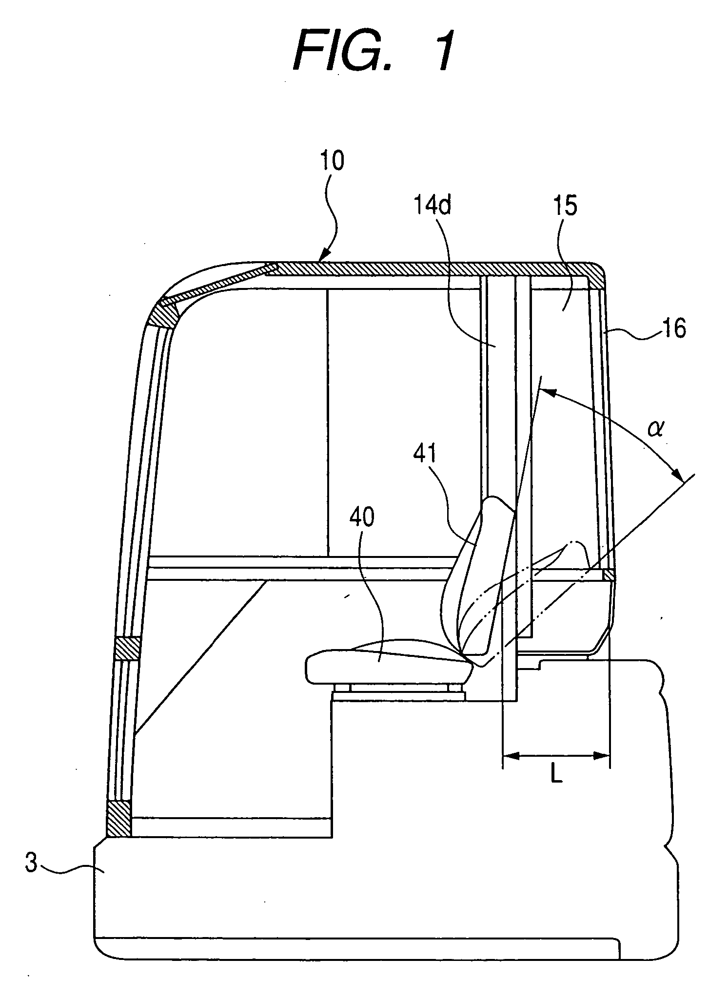
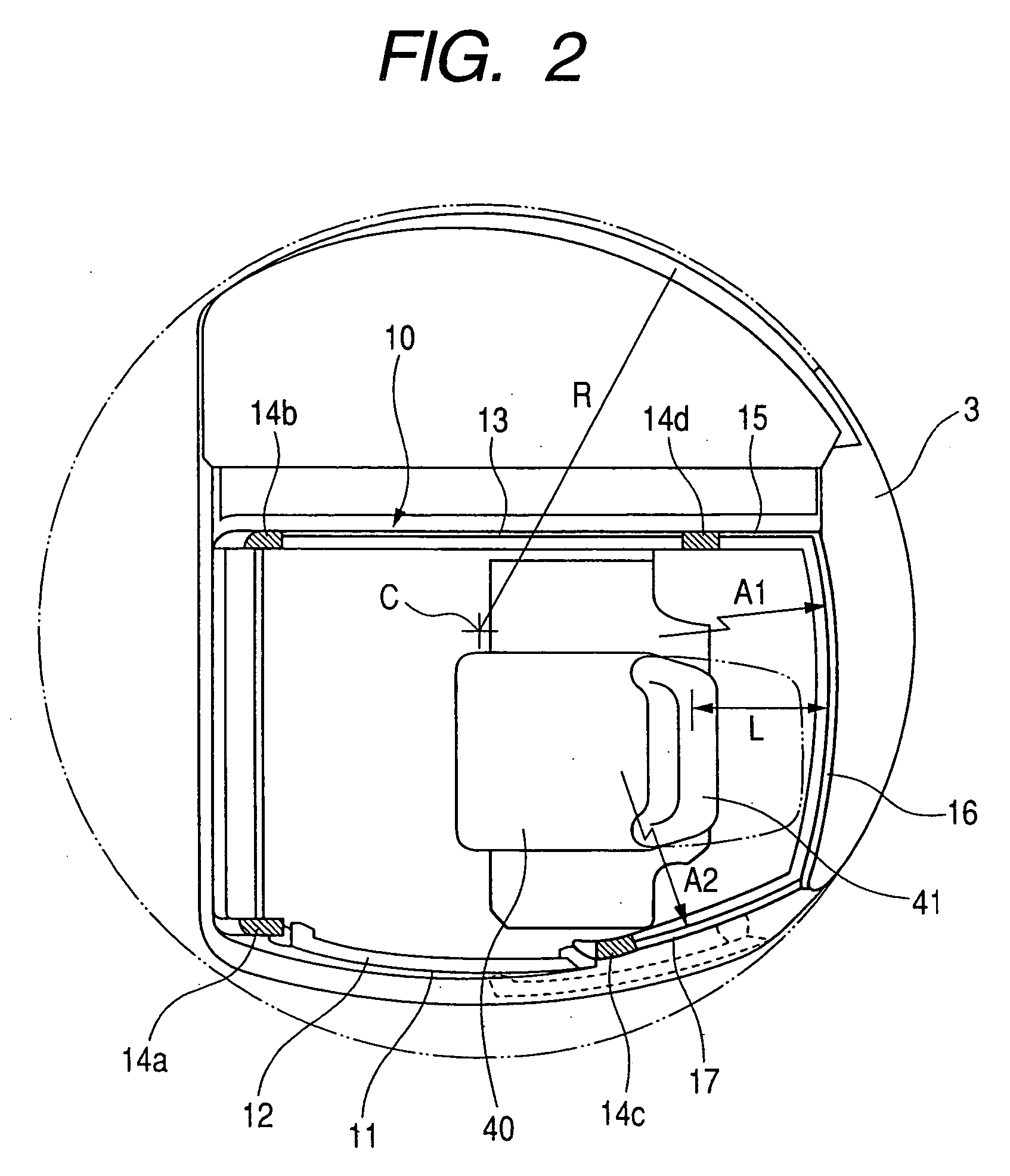
[0013] According to the present invention, the rear side portion of the cab stays within the turning radius of the outer edge portion of the turntable, and is made of rear glass having an outwardly bulging curved surface. Therefore, there is not a fear of causing the cab to contact an outside obstacle when the turntable is swung. Moreover, a clearance between the back of the operator's seat and the rear side portion of the cab can be enlarged, so that it becomes possible to secure a storeroom-forming space sufficiently, increase the seat back reclining angle, and thereby improve the operator's comfort in the cab when he works and rests in the cab. Since the cab has curved surfaces, the external appearance thereof becomes excellent.
[0014] According to the present invention, the radius of curvature of the rear curved glass may be set equal to that of the side curved glass provided at the rear section of the curved surface-carrying outer side portion. In this structure, the same mold can be used when the side curved glass and rear curved glass are molded, so that the cost can be reduced to a lower level.

Problems solved by technology

The clearance M is really too narrow to place, for example, a tool box therein, and proves inconvenient.

Method used


Image

  • Slide door-carrying cab
  • Slide door-carrying cab
  • Slide door-carrying cab

Examples


Embodiment Construction

[0022] A mode of embodiment of the slide door-carrying cab according to the present invention will be described in detail with reference to the drawings. The statement about the cab will be given with such a power shovel as is shown in FIG. 4 taken as an example of a machine to which the present invention is applied.

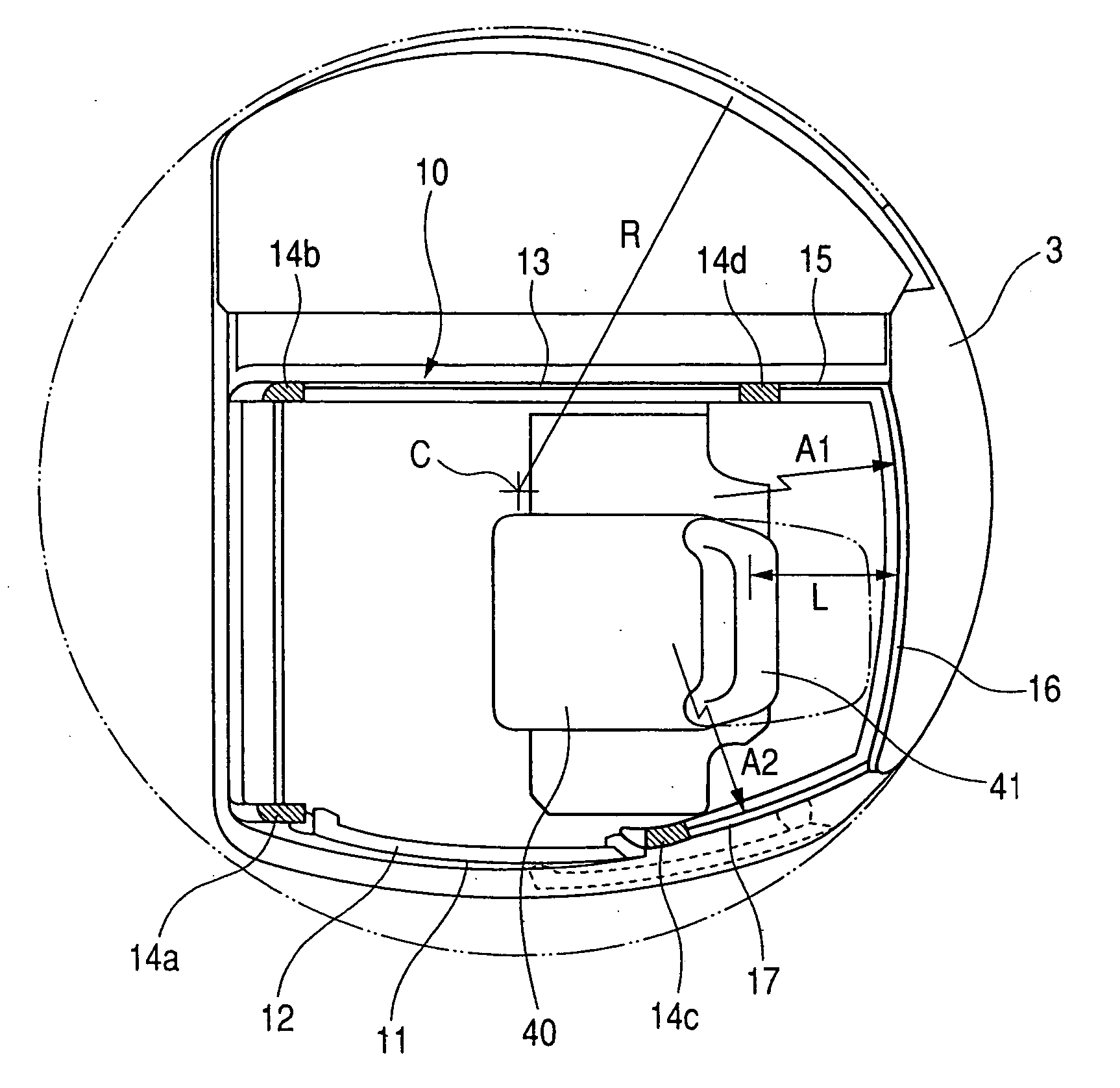
[0023] Referring to FIG. 1 and FIG. 2, a cab 10 is provided in the position on a turntable 3 which is offset from the center C of a swinging movement thereof. An outer side portion 11 constituting a side wall surface of the cab 10 is made so as to have an outwardly bulging curved surface. A slide door 12 opened and closed as the door is moved slidingly along the curved surface is provided at a front section of the outer side portion 11, and a rear wall surface portion at a rear section of the same. An outer edge (a broken line shows the slide door 12 in an opened state) of an orbit of opening and closing movements of the slide door 12 is adapted to stay on the inner sid...


PUM


Abstract

A slide door-carrying cab is provided which includes a slide door capable of forming a sufficient clearance between a rear portion of the cab and a back of an operators seat, reclining the back at a sufficient angle, and giving an excellent comfortableness to an operator. The cab is provided in the position on a turntable which is offset from the center of a swinging movement thereof. An outer side portion of the cab has an outwardly bulging surface, and the slide door which moves along the curved surface is provided at a front section of the outer side portion. A rear portion of the cab is made of outwardly bulging two-dimensionally bent rear curved glass, and an outer edge of the rear portion is made to stay within a turning radius of an outer edge portion of the turntable.

Description

CROSS-REFERENCE TO RELATED APPLICATION [0001] This application is a divisional application of U.S. Ser. No. 10 / 806,408 filed on Mar. 23, 2004, now pending, which application is incorporated herein by reference.BACKGROUND OF THE INVENTION [0002] 1. Field of the Invention [0003] This invention relates to a slide door-carrying cab for construction machines. [0004] 2. Description of the Related Art [0005] The known slide door-carrying cabs for construction machines include the cab for construction machines disclosed in, for example, Japanese patent publication (JP-A-2001-49696), pages 3 to 4, FIGS. 2 and 7. According to this patent publication, a turntable is provided on a traveling gear which is at a lower portion of a construction machine, and a cab in the position on the turntable which is offset from the center of a swinging movement thereof. The cab is formed so that an outer side portion thereof bulges outward curvilinearly. The outer side portion of the cab is provided with a sli...

Claims


Application Information

Patent Timeline
IPC IPC(8): B62D33/06B60J1/00B60J5/00E02F9/16B60J5/06B62D25/08
CPCB60J5/0487B60J5/062B62D33/0617E02F9/166
Inventor SHIOJI, HIROYUKINAMURA, AKIHIDE
Owner KOMATSU LTD
Learn More