
Safety systems for isolating overpressure during pressurized fluid operations

a safety system and pressure relief technology, applied in the field of manifold pressure relief systems, can solve the problems of significant pressure on the components of the fluid flow system, rapid rise in pump pressure, and pressure spikes, and achieve the effects of reducing equipment damage and blowout, reducing pressure, and being more safe and reliabl

Active Publication Date: 2019-01-08
GE OIL & GAS PRESSURE CONTROL
View PDF16 Cites 9 Cited by
  • Summary
  • Abstract
  • Description
  • Claims
  • Application Information

AI Technical Summary

Benefits of technology

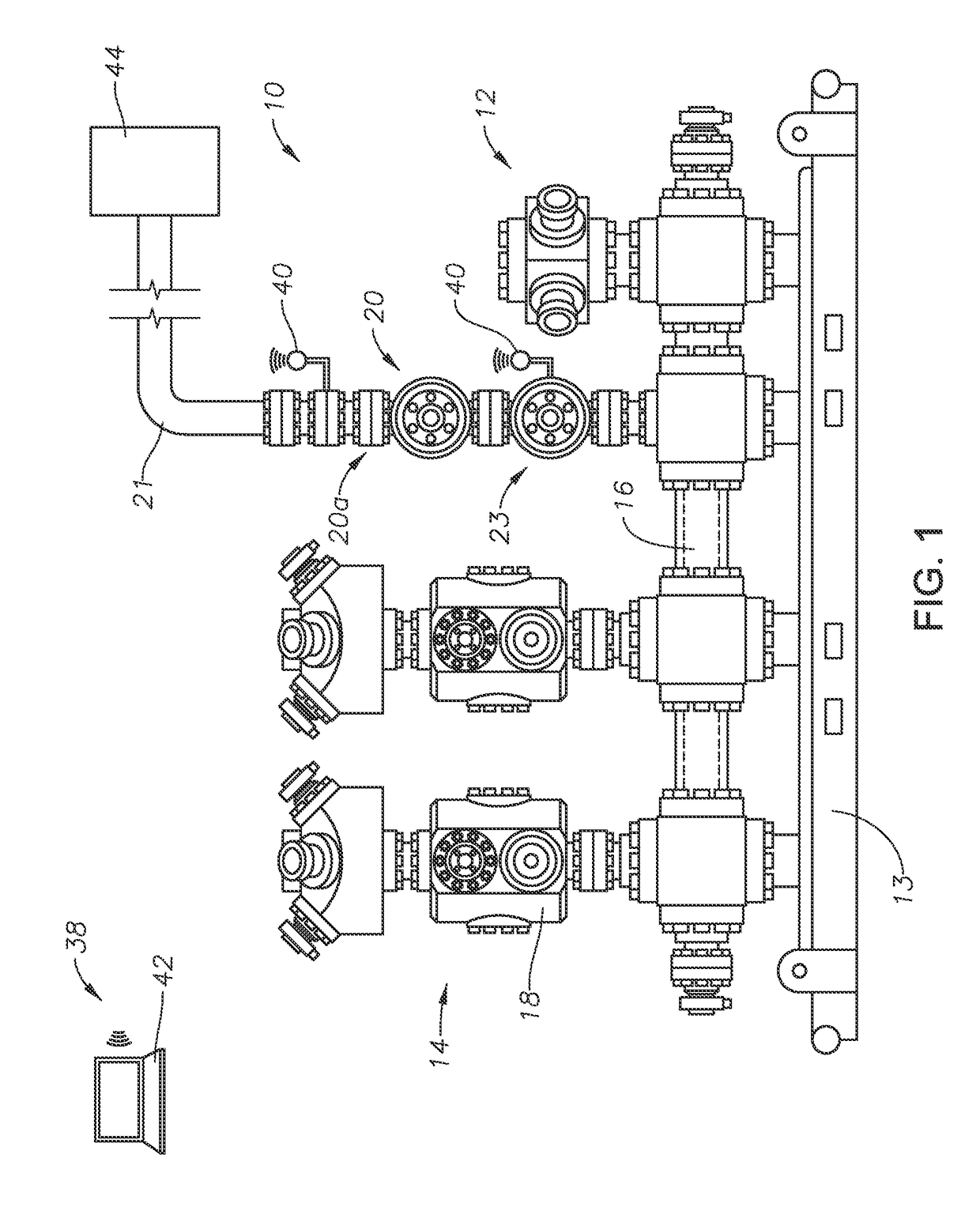
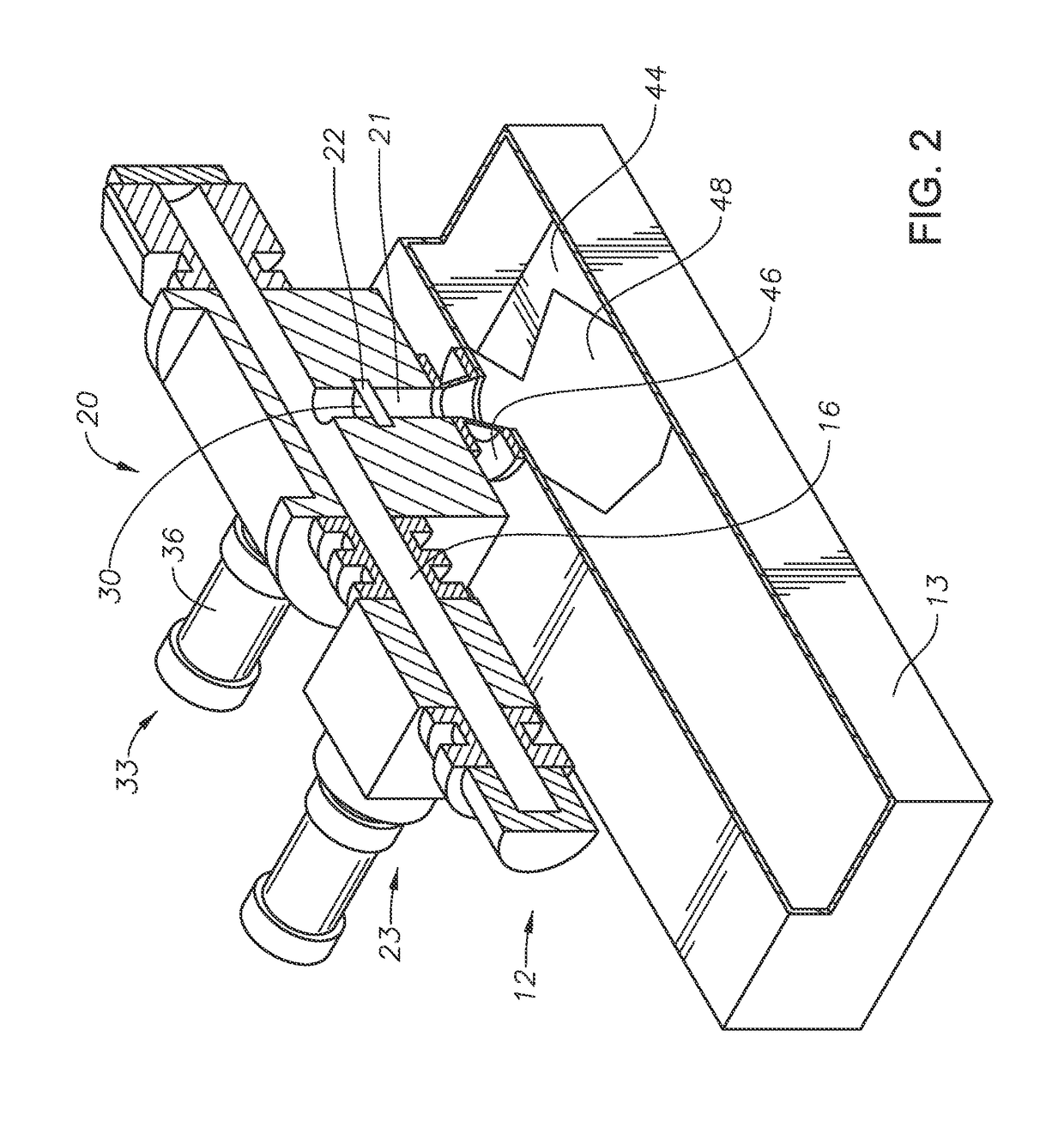
The disclosed system and methods protect expensive components from damage caused by pressure spikes during hydraulic fracturing and other oil and gas drilling operations. It uses an engineered point of failure that is predictable and can be easily replaced. The system includes a control and relief procedure that eliminates the need for shutdowns or deconstruction in the event of an overpressure event. It also ensures that excess pressure can be safely drained to a containment tank and alerts the operator so that they can take appropriate measures to regulate the pressure. Overall, the system provides a safer and more reliable operation and helps to prevent equipment damage and environmental spills during hydraulic fracturing and oil and gas drilling operations.

Problems solved by technology

The bridge partially or fully blocks the flow of treatment fluid and creates a sudden and significant restriction to fluid flow that causes a rapid rise in pump pressure.
In other cases pressure spikes can be attributed to machine faults or human errors such as improper setting of the pumps.
If the pressure spike is not sensed, then the components of the fluid flow system are exposed to a significant pressure, and equipment that is rated below the pressure spike can be damaged.
When fluid pressure exceeds the design pressure, equipment associated with the fluid distribution system at the distribution manifold, down hole, or otherwise, can become damaged.
In addition, when the design pressure is exceeded, a destructive blowout can occur.
This blowout can result in the ejection of components or high pressure fluids, leakage of fluids to the environment, or both.
However the pressures at the truck can be so high that if such a relief system is utilized to relieve pressure, the magnitude of the pressure spike could have already damaged the hydraulic fracturing system equipment, or other associated system components.

Method used


Image

  • Safety systems for isolating overpressure during pressurized fluid operations
  • Safety systems for isolating overpressure during pressurized fluid operations
  • Safety systems for isolating overpressure during pressurized fluid operations

Examples


Embodiment Construction

[0024]The methods and systems of the present disclosure will now be described more fully hereinafter with reference to the accompanying drawings in which embodiments are shown. The methods and systems of the present disclosure may be in many different forms and should not be construed as limited to the illustrated embodiments set forth herein; rather, these embodiments are provided so that this disclosure will be thorough and complete, and will fully convey its scope to those skilled in the art. Like numbers refer to like elements throughout.

[0025]It is to be further understood that the scope of the present disclosure is not limited to the exact details of construction, operation, exact materials, or embodiments shown and described, as modifications and equivalents will be apparent to one skilled in the art. In the drawings and specification, there have been disclosed illustrative embodiments and, although specific terms are employed, they are used in a generic and descriptive sense...


PUM


Abstract

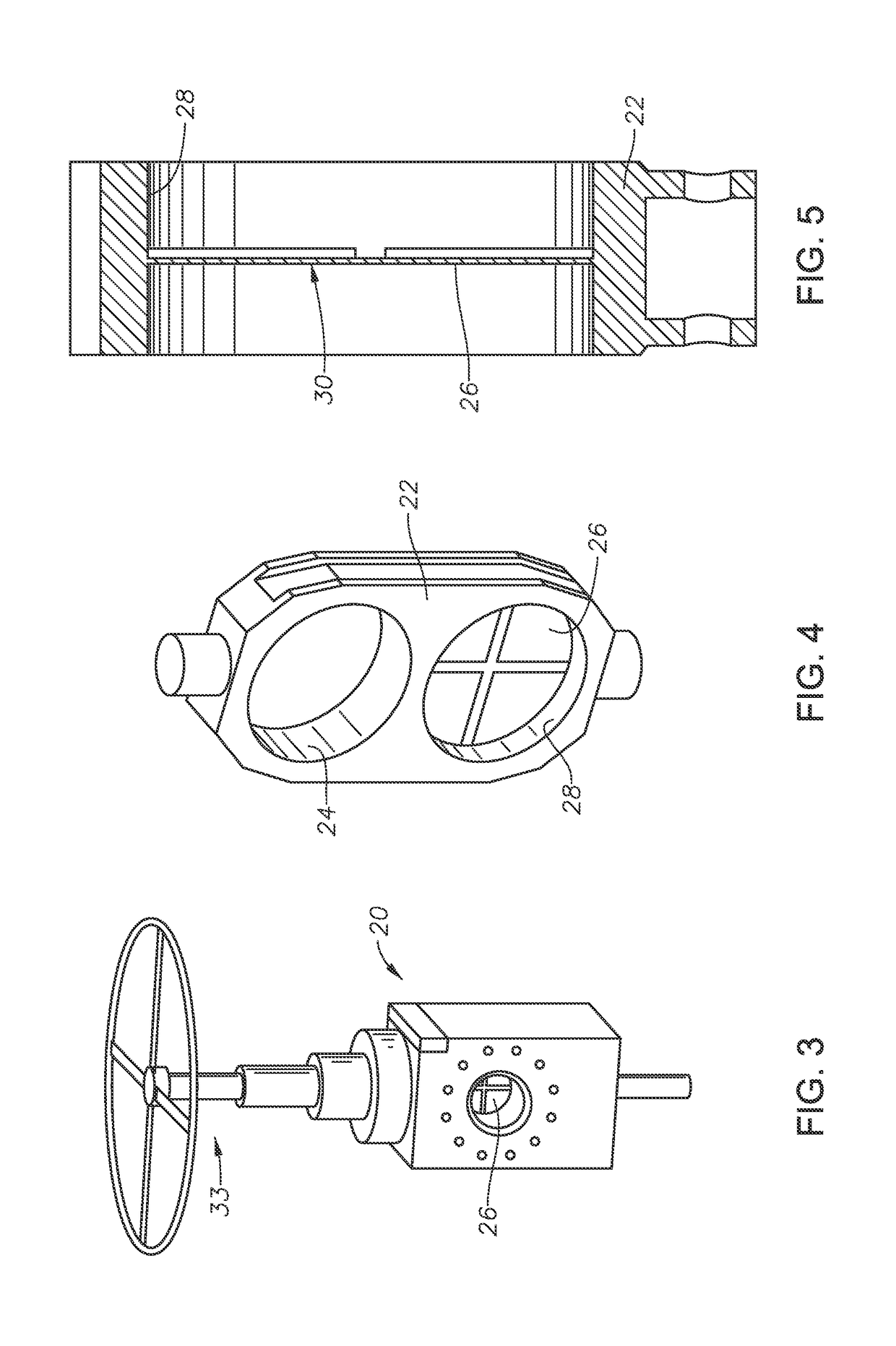
An overpressure safety system for use with a distribution of pressurized fluid associated with hydrocarbon production operations includes a safety valve in fluid communication with a main bore of a fluid control manifold assembly. The safety valve has a blocking condition where the safety valve blocks a flow of pressurized fluid through the safety valve, and a venting condition where the safety valve provides a fluid flow path for the pressurized fluid at a set overpressure to pass through the safety valve. A valve member is moveable within the safety valve between a first position where a pressure side of the valve member blocks the flow of the pressurized fluid at a pressure below the set overpressure from passing through the safety valve, and a second position where the valve member provides a fluid flow path for the pressurized fluid at any pressure to pass through the safety valve.

Description

CROSS REFERENCE TO RELATED APPLICATION[0001]This application claims priority to and the benefit of: U.S. Provisional Application Ser. No. 61 / 978,611 filed Apr. 11, 2014, titled “Safety Systems For Isolating Over Pressure During Pressurized Fluid Operations;” and U.S. Provisional Application Ser. No. 62 / 092,583 filed Dec. 16, 2014, titled “Frac Relief Valve,” the full disclosure of each which is hereby incorporated herein by reference in its entirety for all purposes.BACKGROUND[0002]1. Field of Disclosure[0003]This invention relates in general to systems for controlling the distribution of fluid to one or more wellbores, and in particular to pressure relief systems for manifolds associated with hydrocarbon production systems.[0004]2. Description of Related Art[0005]Certain hydrocarbon production related activities, such as well stimulation and hydraulic fracturing, require the pumping of pressurized fluid down hole. During hydraulic fracturing, as an example, a fluid is pumped into a...

Claims


Application Information

Patent Timeline
Patent Type & Authority Patents(United States)
IPC IPC(8): G05D7/06E21B34/02F16K17/16F16K3/02E21B34/00E21B33/068E21B43/26E21B47/06
CPCE21B34/02E21B33/068E21B34/00E21B43/26F16K3/02F16K17/16E21B47/06G05D7/0635G05D7/0623G05D7/0629E21B43/2607F16K17/04
Inventor KAJARIA, SAURABHRIPPLE, ROBERTMCEVOY, TRAVIS KYLEADAMS, KEITH M.SCHOFIELD, GERALD
Owner GE OIL & GAS PRESSURE CONTROL
Learn More