Current detector

a current detector and detector technology, applied in the field of current detectors, can solve the problems of increasing the size of power converters cannot be reduced, and the height of current detectors is inevitably increased, so as to reduce the occupied volume and reduce the mechanical strength

Active Publication Date: 2019-01-08
FUJI ELECTRIC CO LTD
View PDF11 Cites 1 Cited by
  • Summary
  • Abstract
  • Description
  • Claims
  • Application Information

AI Technical Summary

Benefits of technology

[0009]The present invention has been made to solve the conventional problems described above. An object of the present invention is to provide a terminal block-integrated current detector including a current detection unit and a terminal block merged with each other, while terminal connecting portions ensure sufficient mechanical strength with a reduced occupied volume of the current detection unit and the terminal block integrated together.

Problems solved by technology

The power converter having a typical structure as disclosed in JP 2011-217594A has problems that the size of the power converter cannot be reduced in the direction in which the current detectors and the terminal blocks are arranged and that the height of the current detectors inevitably increases.
Although JP 2013-048539A deals with the conventional problem with the size of the power converter increased in the direction in which the current detectors and the terminal block are arranged, the current detectors still has a problem with the height, which is rather increased since the terminal blocks are arranged above the current detectors.
JP 2013-048539A A has another problem with the structure which complicates the assembling process and is fragile because the power converter includes a plurality of current detectors fixed to the terminal blocks independently via terminal-side power bus bars.
JP 2006-194650A has achieved a decrease of the number of components and a reduction in size of the power converter due to the current sensors serving also as the terminal blocks, but still has a problem with the height of the current sensors.
In addition, JP 2013-048539A and JP 2006-194650A have the common problem that there is only one terminal connection surface provided in the terminal blocks, which requires considerable design modifications if the connection direction of the terminals is necessary to be changed.

Method used


Image

  • Current detector
  • Current detector
  • Current detector

Examples


first embodiment

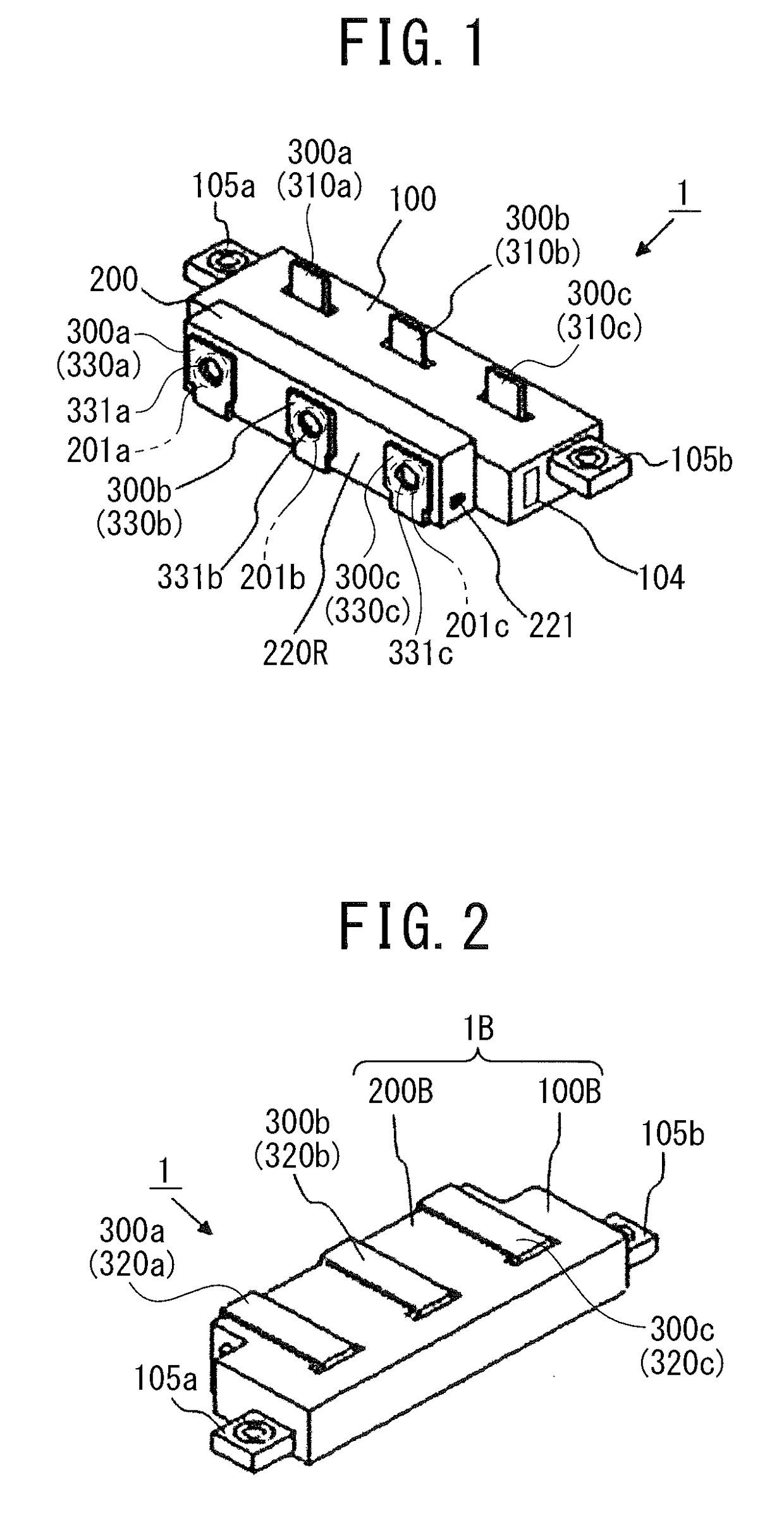
[0022]As illustrated in FIG. 1 and FIG. 2, a current detector 1 according to the first embodiment includes a current detection unit 100, a terminal block 200, and three conductor bars 300a, 300b, and 300c. The current detection unit 100 has a substantially rectangular parallelepiped including an installation surface 100B. As used herein, a direction vertical to the longitudinal direction of the installation surface 100B is referred to as “the height direction”. The installation surface 100B is not always required to be brought in close contact with an opposed surface on which the installation surface 100B is to be placed.

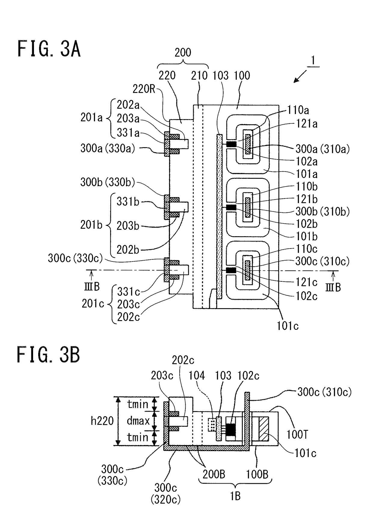
[0023]As illustrated in FIG. 3A and FIG. 3B, the current detection unit 100 includes triple ring-shaped cores 101a, 101b, and 101c made of magnetic material and having gaps 121a, 121b, and 121c, triple magnetic-flux-density detection-elements 102a, 102b, and 102c located in the gaps 121a, 121b, and 121c, a circuit board 103 in which the magnetic-flux-density detecti...

second embodiment

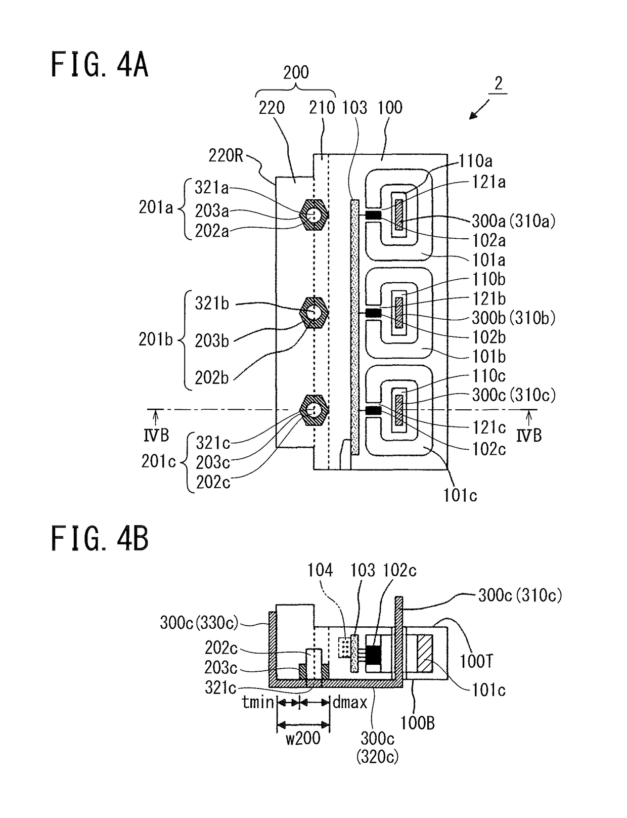
[0043]A current detector 2 according to the second embodiment differs from the current detector 1 according to the first embodiment only in the positions of the triple terminal connecting portions 201a, 201b, and 201c, as illustrated in FIG. 4A and FIG. 4B.

[0044]The terminal connecting portions 201a, 201b, and 201c respectively include triple terminal connection holes 202a, 202b, and 202c having a substantially cylindrical shape provided on the installation surface 200B of the terminal block 200, triple nuts 203a, 203b, and 203c buried in opening ends of the terminal connection holes 202a, 202b, and 202c, and triple penetration holes 321a, 321b, and 321c open on the second conductors 320a, 320b, and 320c of the corresponding conductor bars 300a, 300b, and 300c.

[0045]The width w200, or the length measured in the short-side direction, of the terminal block 200 is set greater than the sum of the resin thickness tmin and the maximum diameter dmax of the terminal connection holes. There...


PUM


Abstract

A current detector includes: a current detection unit including a plurality of cores made of magnetic material, in the plurality of penetration holes are penetrating through, respectively; a terminal block including a plurality of terminal connecting portions being arranged side by side in a direction perpendicular to an axial direction of the penetration holes, the terminal block being merged with the current detection unit; and a plurality of conductor bars, each having one end inserted into one of the penetration holes and another end connected to corresponding one of the terminal connecting portions.

Description

CROSS REFERENCE TO RELATED APPLICATION[0001]This application claims benefit of priority under 35 USC 119 based on Japanese Patent Application No. 2016-109010 filed on May 31, 2016 in Japan, and Japanese Patent Application No. 2016-159524 filed on Aug. 16, 2016 in Japan. The entire contents of the Japanese Patent Applications No. 2016-109010 and No. 2016-159524 are incorporated herein by reference.BACKGROUND OF THE INVENTION1. Field of the Invention[0002]The present invention relates to a current detector merged with a terminal block.2. Description of the Related Art[0003]JP 2011-217594A discloses a power converter including a current detector and a terminal block of a typical configuration. The power converter includes an inverter unit, a current detector, and an output terminal block sequentially arranged on the upper surface of a base of a heat sink. The current detector is arranged such that an axial direction of cores is parallel to the upper surface of the base. Output terminal...

Claims


Application Information

Patent Timeline
Patent Type & Authority Patents(United States)
IPC IPC(8): G01R15/18H02M1/00H02M7/00G01R15/20
CPCG01R15/183G01R15/207H02M7/003H02M1/00H02M2001/0009H02M1/0009
Inventor OKA, ISAOSHINTANI, TAKANORITATSUKAWA, MASAHIRO
Owner FUJI ELECTRIC CO LTD
Why Eureka
Try Eureka