Intracardiac devices comprising stabilizing elements having improved fatigue resistance

a technology of stabilizing elements and stabilizers, which is applied in the field of stabilizers, can solve the problems of still further increases in the value of pre-load force, and achieve the effect of reducing total stress and strain

Inactive Publication Date: 2019-01-22
MVALVE TECH
View PDF23 Cites 102 Cited by
  • Summary
  • Abstract
  • Description
  • Claims
  • Application Information

AI Technical Summary

Benefits of technology

[0010]a) stabilizing wings having at least one portion with a thickness greater than that of the device body;
[0022]In another aspect, the present invention is directed to an intracardiac device as defined hereinabove, wherein said device comprises one or more stabilizing wings, wherein each of said wings comprises one or more primary anchoring arms, which are capable of applying upwards axially-directed stabilizing forces, and one or more support arms. The term “anchoring arm” is used to refer to the portion of the stabilizing wing which comes into contact with, and applies stabilizing forces on, the cardiac tissue. The term “support arm” is used to refer to an auxiliary arm (i.e. an arm or wing in addition to the anchoring arm), the purpose of which is to reduce the total stress and strain exerted by the contracting heart on the aforementioned primary stabilizing arm. In one preferred embodiment, the primary support arm passes medially and either axially upwards or axially downwards (wherein the term “axially” refers to the longitudinal axis of the intracardiac device, which following implantation is coaxial with the longitudinal axis of the heart).
[0029]b) stabilizing wings having one or more leaf springs attached thereto;

Problems solved by technology

Furthermore, increasing the thickness of the presently-disclosed stabilizing wing results in still further increases in the value of the pre-load force.

Method used


Image

  • Intracardiac devices comprising stabilizing elements having improved fatigue resistance
  • Intracardiac devices comprising stabilizing elements having improved fatigue resistance
  • Intracardiac devices comprising stabilizing elements having improved fatigue resistance

Examples


first main embodiment

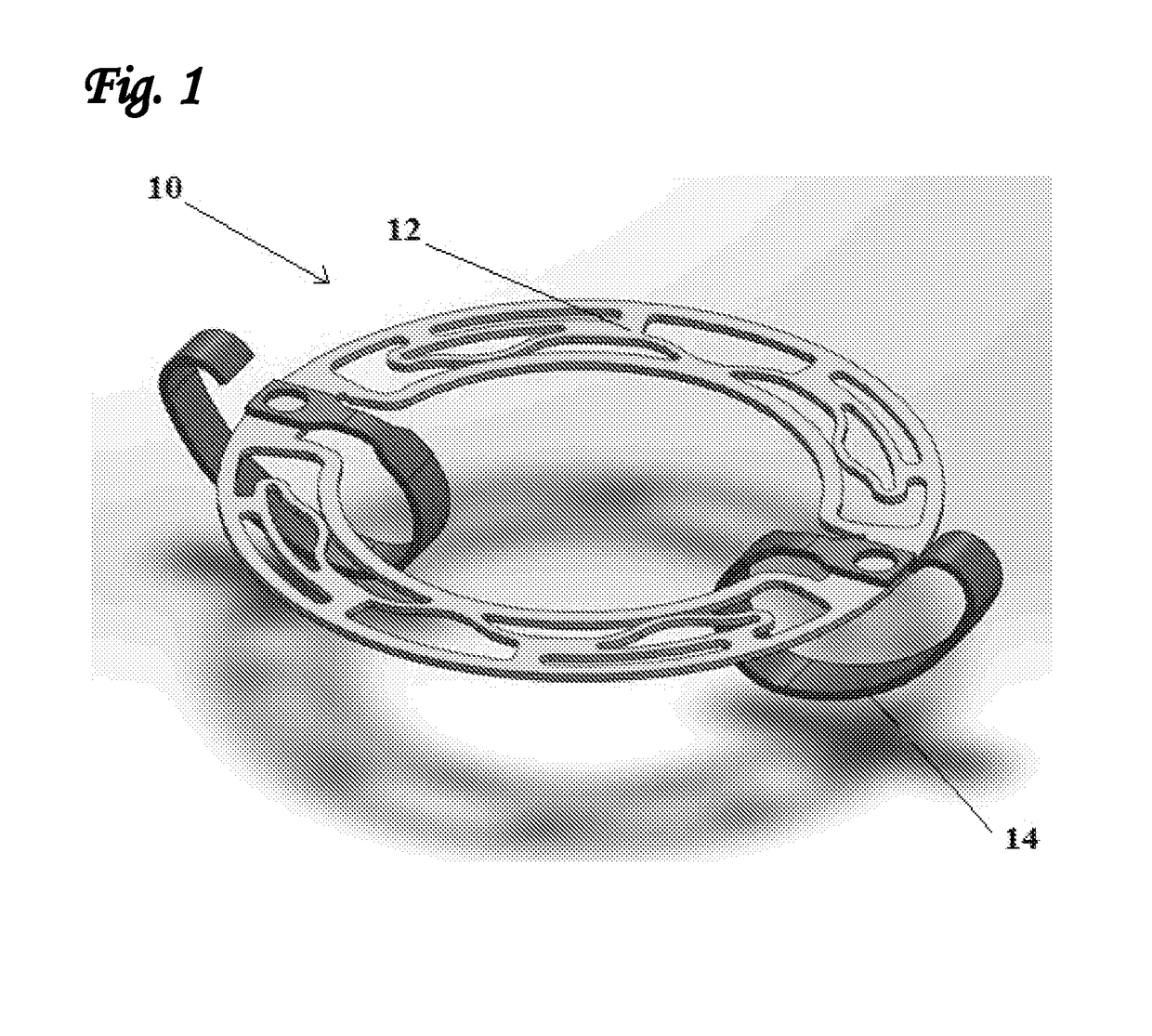
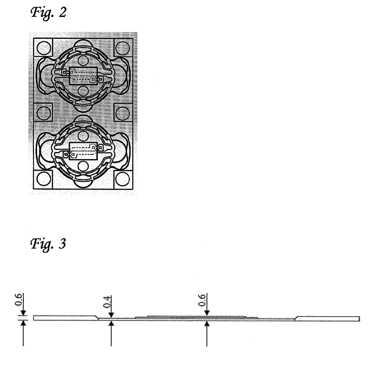
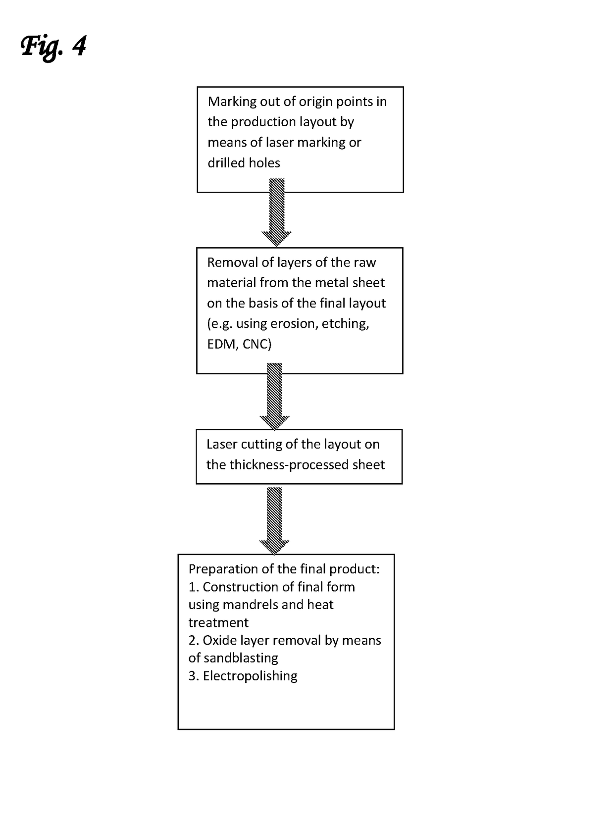
[0073]The present inventors have now found that it is possible to manufacture an intracardiac device in which different regions of said device have different thicknesses. In this way, it is possible to construct a device in which at least a portion of the one or more stabilizing wings is thicker than the body of the device. It has been found by the present inventors that this modification enables the manufacture of an intracardiac device that has greater resistance to displacement following deployment in the heart, as well as a greater resistance to fatigue and fracture, but which does not lead to an increased crossing profile of the crimped device.

[0074]This approach is, in fact, counter-intuitive, since all of the standard manufacturing techniques used to construct intracardiac devices from tubes or sheet metal (e.g. computer-aided design, laser cutting and so on) entirely ignore the thickness of the tube or sheet used. As a consequence, most, if not all devices of this type that ...

second main embodiment

[0108]In this aspect, the present invention is directed to a device suitable in size and form for transcatheter delivery to the mitral valve annulus, wherein said device comprises a device body and one or more stabilizing wings, wherein each of said wings comprises one or more primary anchoring arms, the purpose of which is to apply upwards (wherein in this example—“upwards” refers to a force which is directed from the ventricle towards the atrium) axially-directed stabilizing forces onto the tissues at or near the mitral annulus, preferably in the region of the valve commissures, and one or more auxiliary arms, the purpose of which is to reduce the strain on the primary anchoring arm(s) following deployment of said device. The stabilizing wings will generally also comprise one or more connecting arms for connecting the aforementioned arms to the device body.

[0109]The general arrangement of the various components of the stabilizing wings of the present invention will now be describe...

third main embodiment

[0147]In a further group of embodiments, the stabilizing wings of the intracardiac device further comprise additional elements that serve to improve their fatigue resistance during long-term use. Examples of such additional elements include: wire-covered wings, polymer-sleeve coated wings and wings fitted with leaf springs.

[0148]Thus, in one preferred embodiment of the intracardiac device of the present invention, the stabilizing elements comprise stabilizing wings having a wire coil wound therearound, wherein said wire coil serves to improve the fatigue resistance of said stabilizing wings. While a wire of any suitable material may be used for this embodiment, in one highly preferred embodiment, the wire used is a metal wire, most preferably a Nitinol wire. Alternatively, the wire may be manufactured from a biocompatible polymer including (but not limited to) polyester or Nylon. Preferably, the wire is tightly wound around the stabilizing wings such that there is no fluid-permeable...


PUM


Abstract

The present invention provides an intracardiac device suitable for minimally-invasive delivery, wherein said device comprises a device body and one more stabilizing elements attached to said device body. The stabilizing elements may be selected from the group consisting of: stabilizing wings having at least one portion with a thickness greater than that of the device body, wings comprising one or more auxiliary support arms, wings having a metal wire coil wound around them, wings having a leaf spring attached thereto, polymer-coated stabilizing wings, and mechanical stabilization elements comprising a rotatable jaw-like structure.

Description

[0001]This application is the U.S. national phase of International Application No. PCT / IL2014 / 051030 filed 27 Nov. 2014, which designated the U.S. and claims priority to US Provisional Application Nos. 61 / 910,064 filed 28 Nov. 2013, 61 / 910,066 filed 28 Nov. 2013, 61 / 915,020 filed 12 Dec. 2013, and 62 / 066,929 filed 22 Oct. 2014, the entire contents of each of which are hereby incorporated by reference.FIELD OF THE INVENTION[0002]The present invention relates to stabilizing elements that are suitable for anchoring intracardiac devices within their intended deployment site in the heart. In particular, the stabilizing elements of the present invention are characterized in having significantly greater fatigue-resistance than those previously developed.BACKGROUND OF THE INVENTION[0003]In recent years, many different intracardiac devices aimed at either repairing or replacing dysfunctional mitral valves have been developed. Examples of these include various cardiac valve support devices, t...

Claims


Application Information

Patent Timeline
Patent Type & Authority Patents(United States)
IPC IPC(8): A61F2/24
CPCA61F2/2418A61F2250/0063A61F2250/0036A61F2220/0008A61F2/2409A61F2/2445
Inventor TUBISHEVITZ, AMITDUBI, SHAYBERNSHTEIN, VADIMBUCHBINDER, MAURICE
Owner MVALVE TECH
Why Eureka
Try Eureka