
Modular, wireless optical antenna

a wireless optical antenna and module technology, applied in the field of optical communication, can solve the problems of lack of misalignment tolerance, high cost of lasers on a per watt basis, and high bandwidth, and achieve the effects of low cost, no angular tolerance, and low cos

Active Publication Date: 2019-01-22
8 RIVERS CAPTTAL LLC
View PDF33 Cites 1 Cited by
  • Summary
  • Abstract
  • Description
  • Claims
  • Application Information

AI Technical Summary

Benefits of technology

The modular system provides cost-effective, high-bandwidth connectivity for mobile nodes by eliminating angular tolerance issues and enhancing range and throughput through the use of high-power transmitters and wide field-of-view receivers, facilitating continuous communication across a mesh network.

Problems solved by technology

Optical wireless communications systems today despite providing much higher bandwidth have found only niche applications due to the necessity for line-of-sight operation, high atmospheric attenuation over the wireless channel especially in fog, the high cost of lasers on a per watt basis, and lack of misalignment tolerance necessitating the addition of high-cost pointing and tracking systems.
However, such implementations provide only limited ranges and are proposed with components with limited modulation rates which limits throughput and therefore have limited applications, such as indoor local area networks (LANs) or other confined spaces.
Other teachings contemplate 360 degree transmit coverage with mirrors but do not address detector field-of-view.

Method used


Image

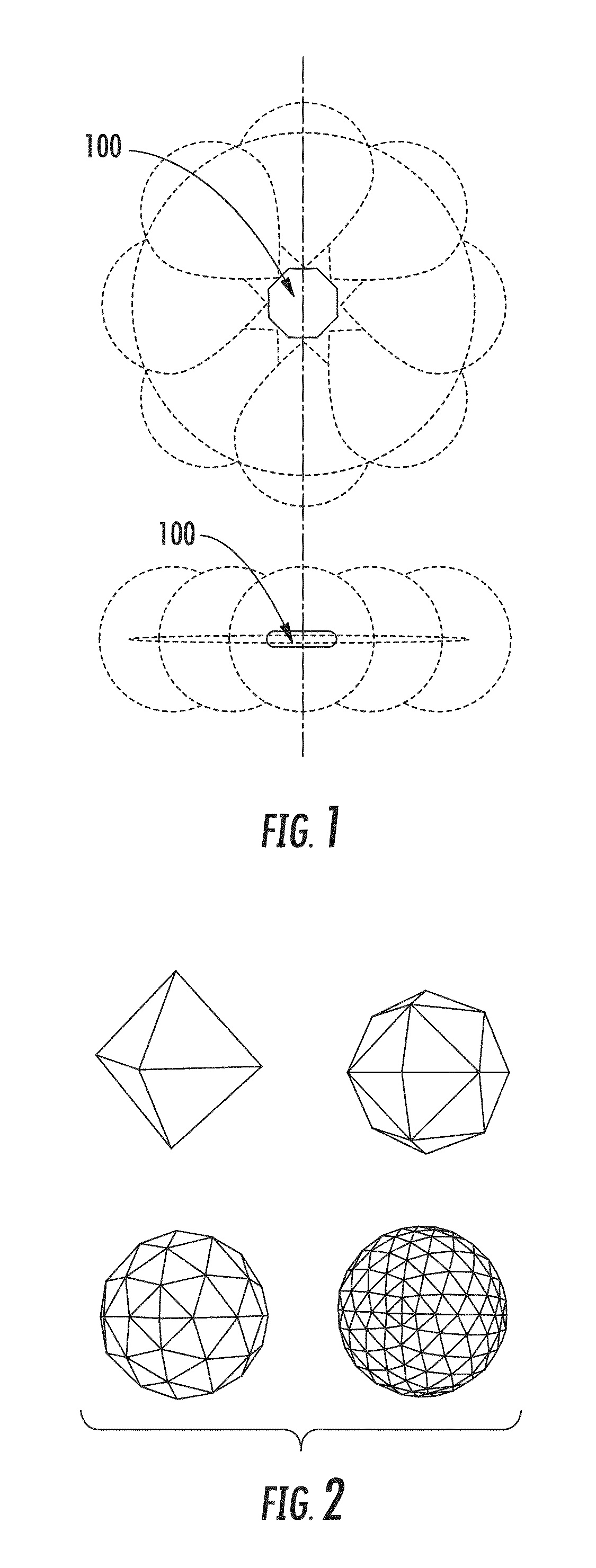
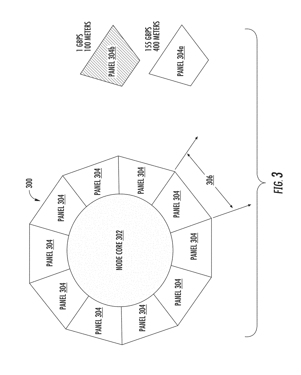
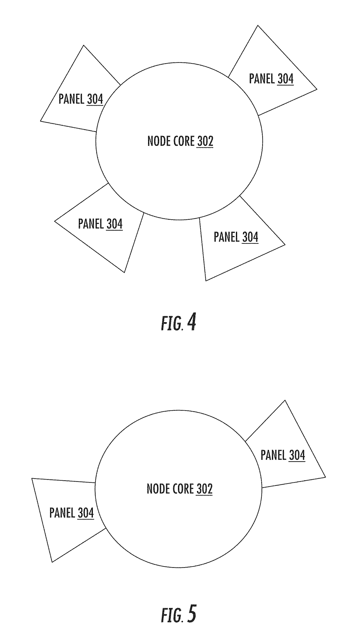
  • Modular, wireless optical antenna
  • Modular, wireless optical antenna
  • Modular, wireless optical antenna

Examples


Embodiment Construction

[0039]The present disclosure will now be described more fully hereinafter with reference to example implementations thereof. These example implementations are described so that this disclosure will be thorough and complete, and will fully convey the scope of the disclosure to those skilled in the art. Indeed, the disclosure may be embodied in many different forms and should not be construed as limited to the implementations set forth herein; rather, these implementations are provided so that this disclosure will satisfy applicable legal requirements. As used in the specification and the appended claims, for example, the singular forms “a,”“an,”“the” and the like include plural referents unless the context clearly dictates otherwise. Also, for example, reference may be made herein to quantitative measures, values, relationships or the like. Unless otherwise stated, any one or more if not all of these may be absolute or approximate to account for acceptable variations that may occur, ...


PUM


Abstract

A modular node for an optical communication network includes one or more transceiver modules of a plurality of transceiver modules, and a node core including a plurality of electrical connectors to electrically join up to the plurality of transceiver modules to the node core. At least some of the transceiver modules has an optical transceiver configured to emit optical beams carrying data and without artificial confinement, and detect optical beams emitted and without artificial confinement. The up to the plurality of transceiver modules electrically joined to the node core are spatially separated to provide configurable coverage for optical communication based on their number and placement. And the node core further includes switching circuitry configured to connect the one or more transceiver modules to implement a redistribution point or a communication endpoint in the optical communication network.

Description

CROSS-REFERENCE TO RELATED APPLICATION(S)[0001]The present application claims priority to U.S. Provisional Patent Application No. 62 / 304,680, entitled: Modular, Wireless Optical Omni-Antenna, filed on Mar. 7, 2016, the content of which is incorporated herein by reference in its entirety.TECHNOLOGICAL FIELD[0002]The present disclosure relates generally to optical communications and in particular, diverged-beam optical communications.BACKGROUND[0003]Optical wireless communications systems today despite providing much higher bandwidth have found only niche applications due to the necessity for line-of-sight operation, high atmospheric attenuation over the wireless channel especially in fog, the high cost of lasers on a per watt basis, and lack of misalignment tolerance necessitating the addition of high-cost pointing and tracking systems. To overcome the misalignment problem, omni-directional optical wireless antennas (“omni-antennas”) have been proposed that send and receive optical w...

Claims


Application Information

Patent Timeline
Patent Type & Authority Patents(United States)
IPC IPC(8): H04B10/27H01Q5/22H04B10/40H04B10/112H04B10/114H04W84/18
CPCH04B10/27H01Q5/22H04B10/1129H04B10/1149H04B10/40H04B10/1143H04W84/18
Inventor ADAMS, MICHAEL W.BROWN, WILLIAM J.ZHOU, DAYONGCLARK, HANNAH
Owner 8 RIVERS CAPTTAL LLC
Learn More