Systems and methods of generating energy from solar radiation

a technology of solar radiation and solar energy, applied in solar heat systems, heat collector mounting/support, light and heating equipment, etc., can solve the problems of ineffective large-scale use of solar panels, prohibitive costs associated with such large-scale usage, and low cost of current solar panels

Inactive Publication Date: 2016-07-14
COMBINED POWER LLC DBA HYPERLIGHT ENERGY
View PDF7 Cites 1 Cited by
  • Summary
  • Abstract
  • Description
  • Claims
  • Application Information

AI Technical Summary

Benefits of technology

[0011]In general terms, the present disclosure provides a solar reflector assembly useable for generating energy from solar radiation. Embodiments of the solar reflector assemblies are elongated tubes of rigid or semi-rigid material with each tube including a reflective material to reflect solar radiation to a solar collector. This structure and the materials employed provide significant cost savings for manufacture, shipping and deployment of the solar reflector assemblies. The solar reflector assembly is configured to be deployed on a supporting body of liquid. This provides both liquid ballasting capability and structural support. Beneficially, the solar reflector assemblies are inexpensive to manufacture, deploy and operate, providing a cost effective solution for energy generation.
[0013]In exemplary embodiments, the reflective material can be configured to reflect substantially all solar radiation towards the solar collector. In another exemplary embodiment, the reflective material can be configured to substantially reflect a first prescribed wavelength range towards a solar collector and to substantially transmit a second prescribed wavelength range therethrough. One end cap assembly may be coupled to the elongated tube, or a pair of end cap assemblies can be coupled to the elongated tube, in which at least one of the end cap assemblies is configured to facilitate the flow of gas and / or liquid into and out of the elongated tube.
[0027]To minimize cost, tubes may be made using common plastic extrusion equipment and standard polymer resins such as PVC, ABS, Acrylic and other resins. Traditional plastic extrusion equipment is not designed to hold angular twist tolerances over long lengths. Even when extreme care is taken, plastic extrusions are often not straight enough to use in concentrated solar systems because they do not produce optical accuracy sufficient for hitting a target.
[0032]It is advantageous to use standard low cost plastic resins and extrusion equipment, but a long length, polymer pipe with reflector mounted on top can be formed in other ways as well, this invention covers a long, semi-rigid, polymer pipe, with a reflective surface mounted on top, which is field-configurable to serve as a solar reflector.

Problems solved by technology

However, current solar panel technology has been ineffective for large-scale uses, such as electrical generation sufficient for municipal applications.
The costs associated with such large-scale usages have been prohibitive.
Current solar panels are relatively expensive and do not allow cost-effective energy storage.
Although such CSP systems are better than traditional flat-panel photovoltaic cells for large-scale applications, shortfalls exist.
For example, glass and metal reflector assemblies are expensive.
Further, current tracking devices used with CSP can be relatively expensive and complicated.
As a result, current approaches have yet to achieve significant market penetration because of cost issues.
However, such systems can be expensive and, in many instances, cost prohibitive.

Method used


Image

  • Systems and methods of generating energy from solar radiation
  • Systems and methods of generating energy from solar radiation
  • Systems and methods of generating energy from solar radiation

Examples


Embodiment Construction

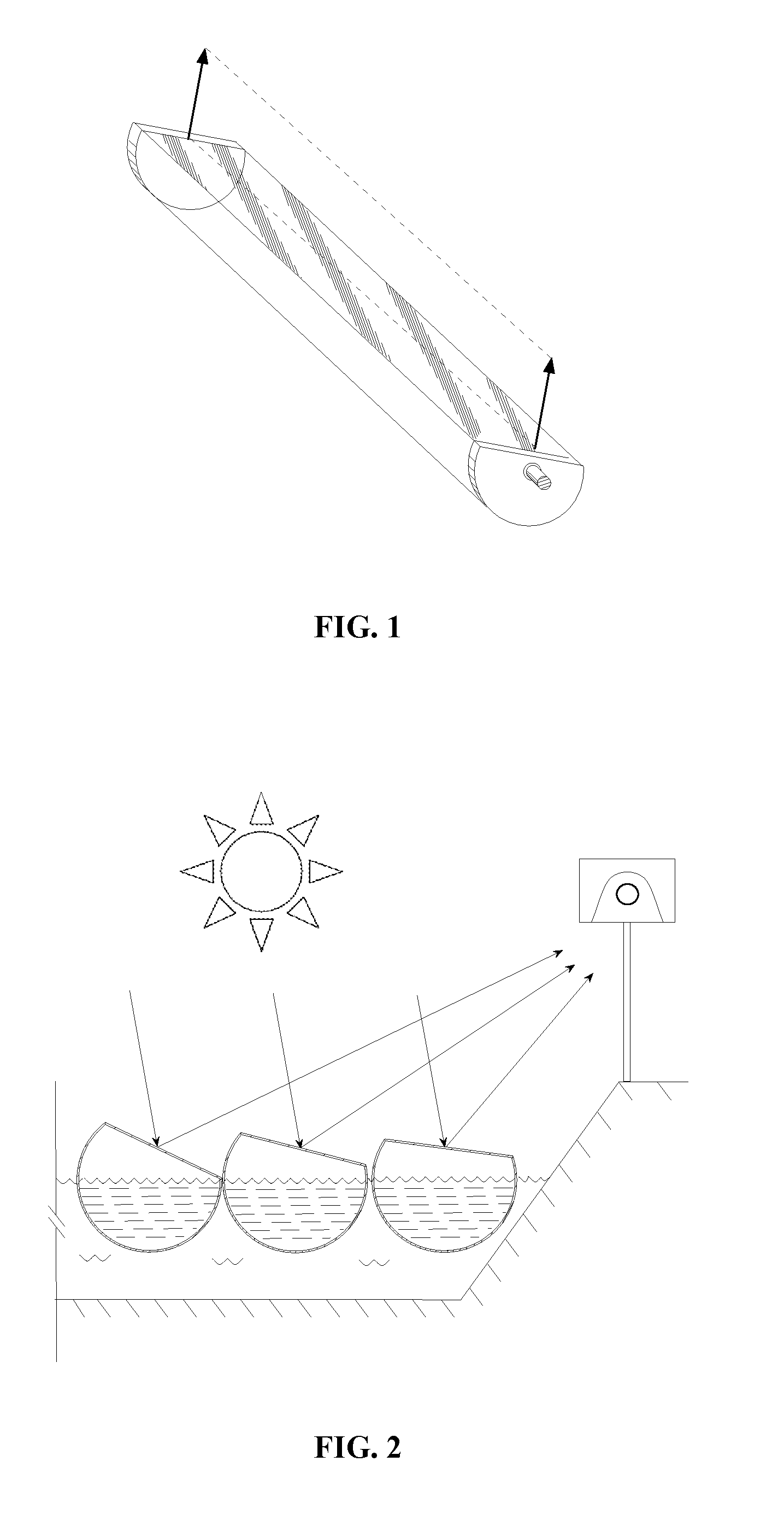
[0045]With reference now to the drawings, and particularly FIG. 1 there is shown a perspective view of a single tube with a flat section onto which a reflective material is attached. Arrows indicate a vector normal to the reflector plane at each end of the pipe. Such pipe may be rotated to reflect a beam of light that will hit a target as indicated by the dashed line between the arrow heads. This is an idealized view of a polymer pipe section that has been manufactured perfectly, and has no twist along its length.

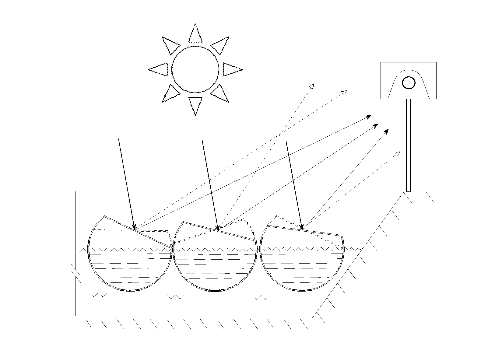
[0046]With reference now to FIG. 2, there is shown a cross section of an array of solar reflector assemblies in a constructed pool. In the idealized case from FIG. 1, the beams of light reflected by the individual tube elements will strike the target uniformly, as shown in the figure.

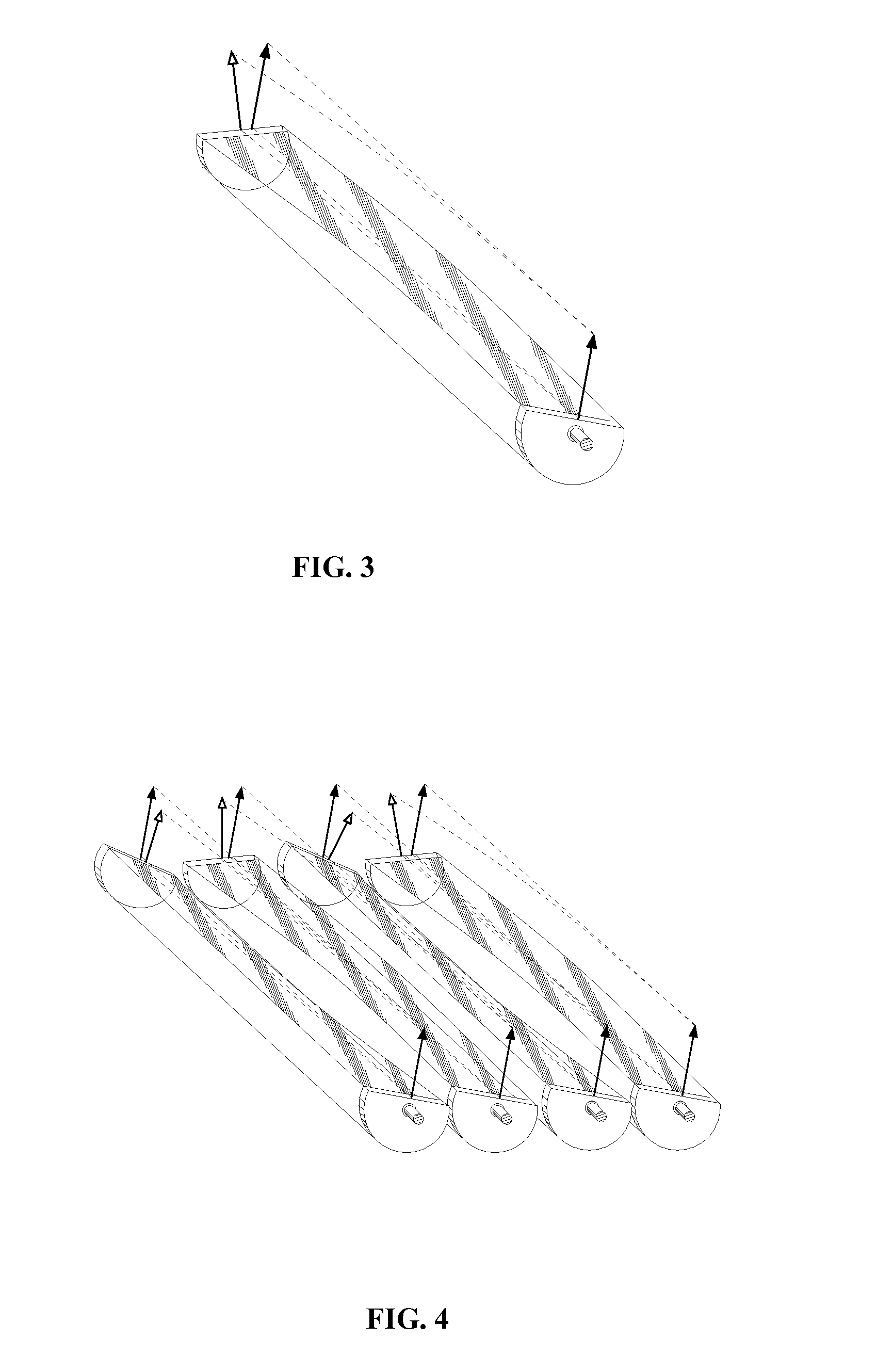
[0047]With reference now to FIG. 3, there is shown a perspective view of a single tube with a flat section onto which a reflective material is attached. The pipe is twisted. It can be seen in t...


PUM


Abstract

A solar reflector assembly is provided for generating energy from solar radiation. The solar reflector assembly is configured to be deployed on a supporting body of liquid and to reflect solar radiation to a solar collector. The solar reflector assembly has an elongated tube having an inner portion to facilitate liquid ballast, made of semi-rigid material and a flat section built into a wall of the tube or attached to the wall of the tube. A reflective material attached to said flat section of the wall of the tube to reflect solar radiation. The elongated tube has an axis of rotation oriented generally parallel to a surface of a supporting body of liquid. The elongated tube may be elastically or plastically deformed by application of a torque along its length, so as to bring flat-surface normal vectors at each end of the tube largely into alignment with each other.

Description

CROSS-REFERENCE TO RELATED APPLICATION[0001]This application claims priority to and benefit of U.S. Patent Application Ser. No. 61 / 873,714, filed Sep. 4, 2013, which is hereby incorporated by reference in its entirety.FIELD OF THE DISCLOSURE[0002]The present disclosure relates to solar energy systems.BACKGROUND OF THE DISCLOSURE[0003]There has been a long-standing need to provide energy generation from renewable sources. Various renewable energy sources have been pursued, such as solar energy, wind, geothermal, and biomass for biofuels as well as others.[0004]Solar radiation has long been a prime candidate for fulfilling this need. Various approaches have been taken to achieve energy generation from solar radiation. Towards that end, much focus has been directed to creating a low cost solar energy conversion system that functions with high efficiency and requires little maintenance.[0005]For example, solar panels formed of photovoltaic cells (solar cells) are used to transform light...

Claims


Application Information

Patent Timeline
Patent Type & Authority Applications(United States)
IPC IPC(8): F24J2/52F24J2/38F24S50/20
CPCF24J2/38F24J2/5267C12M23/02C12M23/06C12M23/26C12M23/50C12M31/02C12M31/08Y02E10/47F24S30/425F24S2023/872F24S23/82F24S2025/02F24S20/70F24S23/77F24S50/20C12M21/02F24S30/42
Inventor KING, JOHN D. H.KRAMER, NICHOLAS A.TANG, ERIK E.OLSEN, KRISTOFER J.
Owner COMBINED POWER LLC DBA HYPERLIGHT ENERGY
Why Eureka
Try Eureka