Apparatus and methods for controlling insertion of a membrane channel into a membrane

a technology an apparatus, which is applied in the field of apparatus and methods for controlling the insertion of a membrane channel into a membrane, can solve the problems of inability to provide a dedicated computer control unit per channel, inability to achieve the effect of adsorption of nanopores to the walls of the vessel, and high cost of circuits, so as to reduce the reaction time of the device, increase the overall amount of time for required, and good single channel yield

Pending Publication Date: 2020-06-11
OXFORD NANOPORE TECH PLC
View PDF0 Cites 0 Cited by
  • Summary
  • Abstract
  • Description
  • Claims
  • Application Information

AI Technical Summary

Benefits of technology

[0008]While the use of computer controlled automation of a stimulus, such as applied potential, is beneficial over the more manual methods of controlled pore insertion, they have a number of features that are undesirable. One such feature is the need for a computer, or similar decision making circuit, to perform the operation of removing or reducing the pore insertion stimulus. Such circuits are expensive and may not be practical when dealing with a large array of membranes. Each membrane must be subject to this process of computer control to ensure good single channel yield and must either be connected to a dedicated computer control unit or must share a computer control unit between other membranes. Providing a dedicated computer control unit per channel is expens

Problems solved by technology

While the use of computer controlled automation of a stimulus, such as applied potential, is beneficial over the more manual methods of controlled pore insertion, they have a number of features that are undesirable.
Such circuits are expensive and may not be practical when dealing with a large array of membranes.
Providing a dedicated computer control unit per channel is exp

Method used


Image

  • Apparatus and methods for controlling insertion of a membrane channel into a membrane
  • Apparatus and methods for controlling insertion of a membrane channel into a membrane
  • Apparatus and methods for controlling insertion of a membrane channel into a membrane

Examples


Embodiment Construction

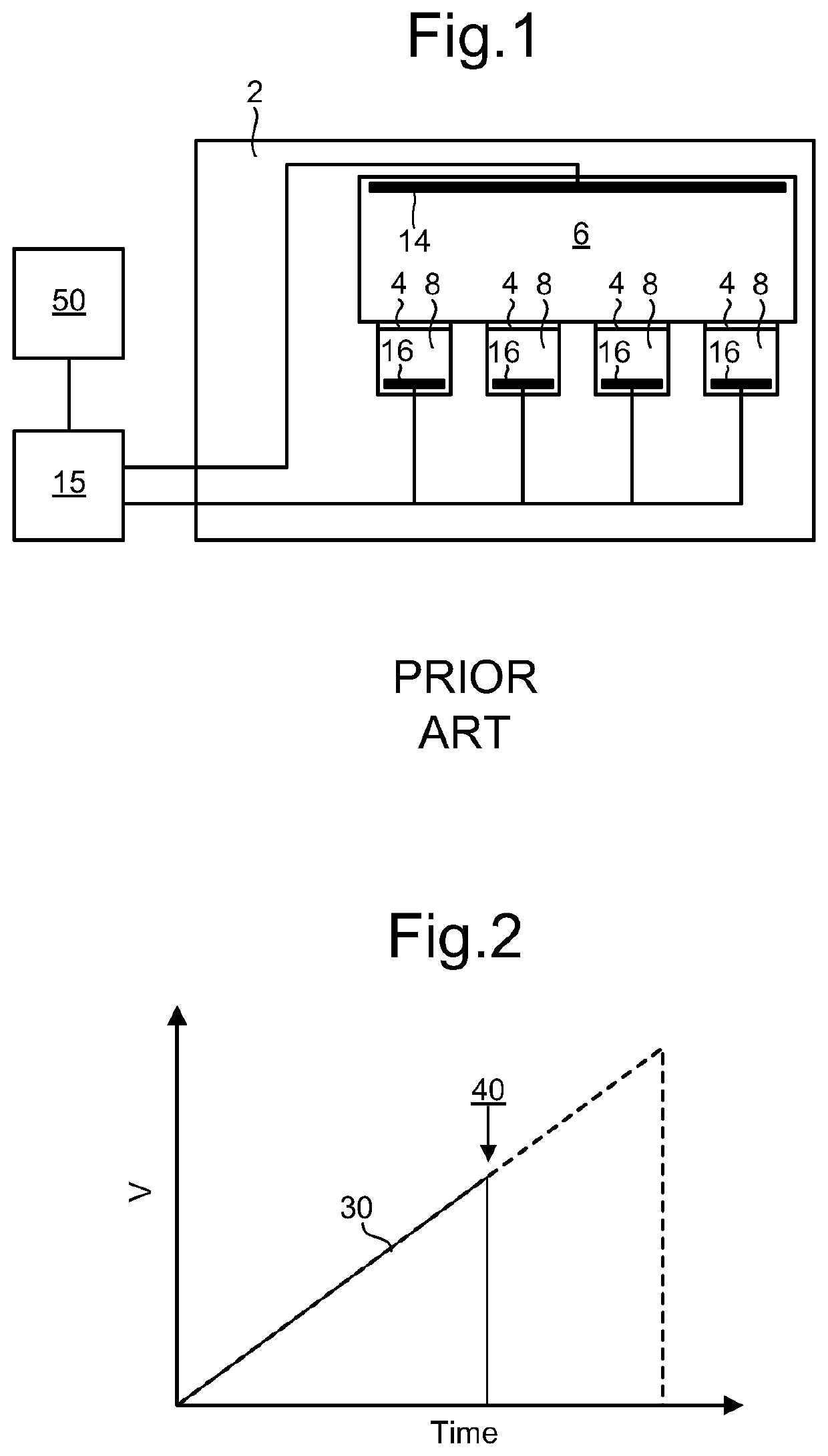
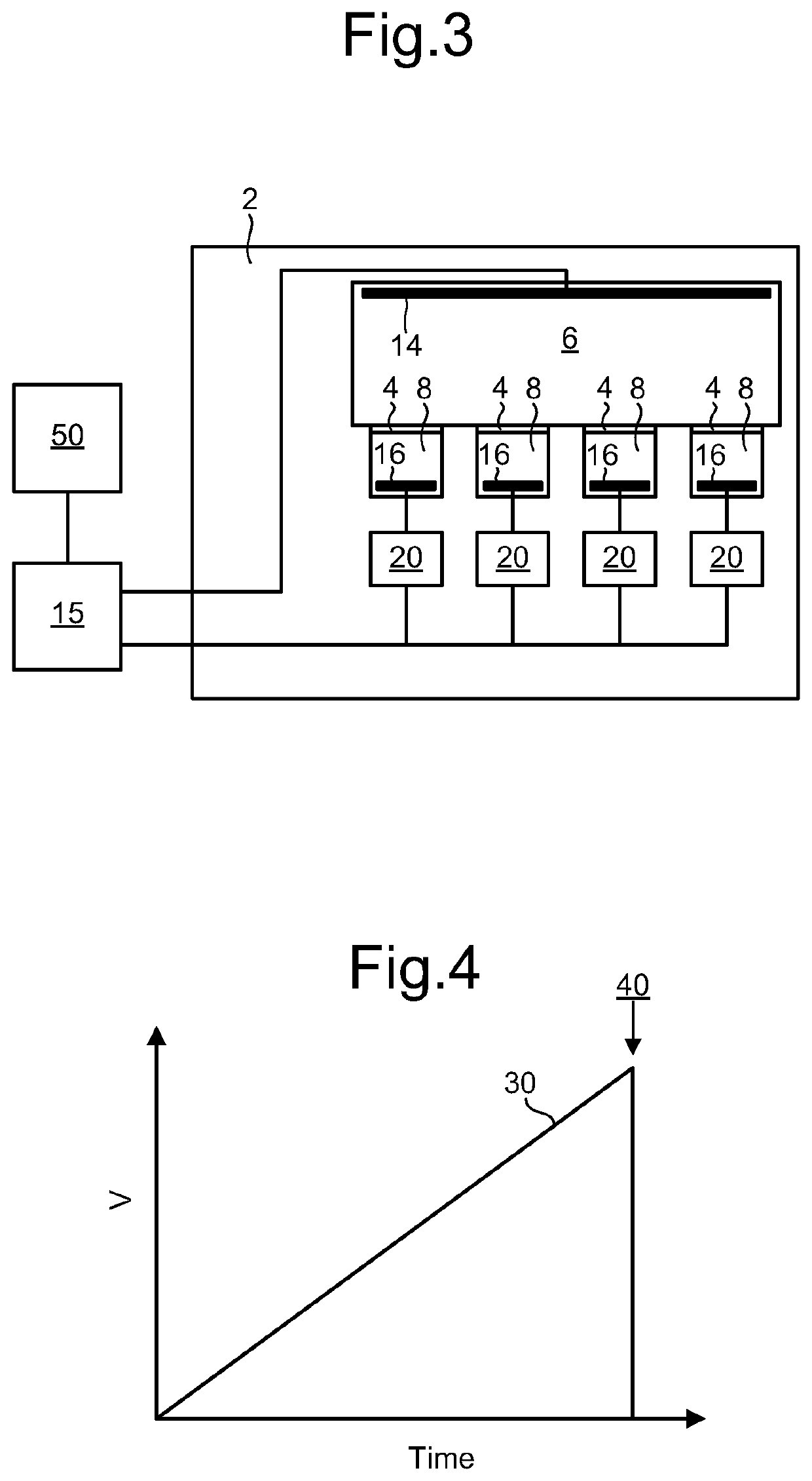
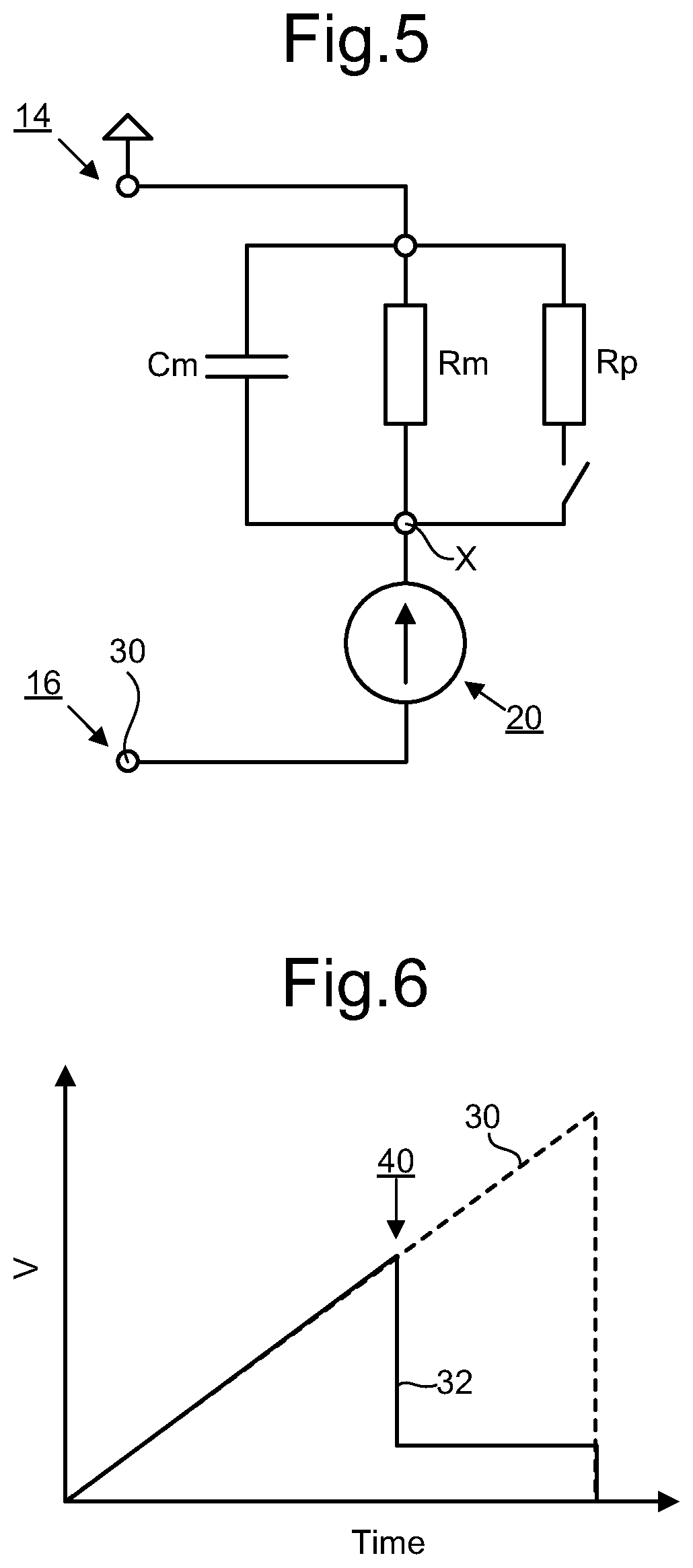
[0050]This disclosure generally relates to systems and methods for controlling the insertion of a membrane channel into a membrane. In some embodiments, the membrane separates a first liquid from a second liquid. In some embodiments, a driving unit applies a potential difference across the membrane via a first electrode contacting the first liquid and a second electrode contacting the second liquid, to promote insertion of a membrane channel into the membrane from the first liquid or the second liquid. In some embodiments, a membrane voltage reduction unit, connected in series with the membrane, is configured such that a reduction in resistance through the membrane caused by insertion of a membrane channel intrinsically increases a potential difference across the membrane voltage reduction unit, thereby lowering the applied potential difference across the membrane, in some cases sufficiently to prevent or reduce a probability of insertion of a further membrane channel.

[0051]FIG. 3 d...


PUM

PropertyMeasurementUnit
Timeaaaaaaaaaa
Timeaaaaaaaaaa
Amphiphilicaaaaaaaaaa

Abstract

Apparatus and methods for controlling the insertion of a membrane channel into a membrane are disclosed. In one arrangement a first bath holds a first liquid in contact with a first surface of a membrane. A second bath holds a second liquid in contact with a second surface of the membrane. The membrane separates the first and second liquids. A first electrode contacts the first liquid. A second electrode contacts the second liquid. A driving unit applies a potential difference across the membrane via the first and second electrodes to promote insertion of a membrane channel into the membrane from the first liquid or the second liquid. A membrane voltage reduction unit is connected in series with the membrane. The driving unit applies a driving voltage across the membrane voltage reduction unit and the membrane, the driving voltage providing the potential difference across the membrane. The membrane voltage reduction unit is configured such that a reduction in resistance through the membrane caused by insertion of a membrane channel intrinsically increases a potential difference across the membrane voltage reduction unit thereby lowering the potential difference across the membrane. The lowering of the potential difference across the membrane is sufficient to prevent or reduce promotion of insertion of a further membrane channel.

Description

FIELD OF THE INVENTION[0001]The invention relates to apparatus and methods for controlling the insertion of a membrane channel into a membrane.BACKGROUND[0002]Channels formed across membranes can be used to sense molecular entities. Interactions between the molecular entities and the channel can cause characteristic modulations of a signal. By monitoring this signal it is possible to detect the characteristic modulations and thereby sense the molecular entities. A variety of technologies have been proposed based on this principle, such as disclosed in WO2008102120, WO2009035647, WO200079257, WO200142782 and WO2007057668. An example of such is the measurement of a current signal due to the flow of ions through a membrane channel. The membrane separates two solutions wherein the membrane channel provides a transport path through the membrane between the solutions. The membrane is highly resistive such that the sole transport pathway between the solutions is through the membrane channe...

Claims


Application Information

Patent Timeline
IPC IPC(8): B01L3/00B81C1/00
CPCB01L3/502B01L2300/044B81C1/00071B01L2400/0415G01N33/48721
Inventor GARALDE, DANIELCLARKE, JAMESJENNISON, MIKEHERON, ANDREW
Owner OXFORD NANOPORE TECH PLC
Why Eureka
Try Eureka