
Current transformer system with sensor CT and generator CT separately arranged in parallel in electric power line, and integrated system for controlling same in wireless communications network

a current transformer and generator technology, applied in the field of current transformer systems, can solve the problems of many limitations in simultaneously coupling without gaps, interference between, and the above-described current transformer has the following limitations, so as to maximize the convenience of power supply and facilitate the need for power. , the effect of maximizing the safety of workers

Inactive Publication Date: 2019-01-29
FERRARIS INC
View PDF46 Cites 4 Cited by
  • Summary
  • Abstract
  • Description
  • Claims
  • Application Information

AI Technical Summary

Benefits of technology

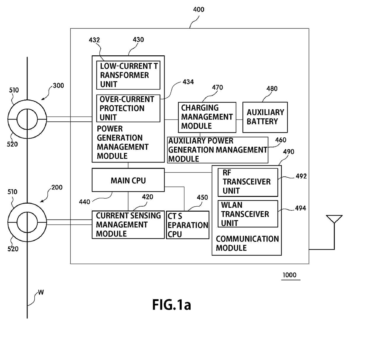
The present patent text describes a new configuration that allows for a more efficient and flexible power supply system. It uses a separable generator as the main power source, which makes power supply convenient and easy to adjust as needed. The system also includes a monitoring function to help detect and prevent power usage issues in real time. Additionally, the system allows for real-time communication and separation of the generator from the wire, which improves safety and management of the current transformer system.

Problems solved by technology

However, the above-described current transformer has the following limitations.
Firstly, since current sensing CT used as a sensor is not suitable for charging a battery, there is a need to use a battery used as a main power source.
To this end, there is an attempt to use a portion of the current sensing CT but it causes the interference between the core of a power generating CT and the core of a current sensing CT.
However, since such a case also employs coupling two cores to a single structure, there are many limitations in simultaneously coupling without a gap when the two separable cores are installed at a wire.
Thirdly, when the above-described magnetic structure is demolished in order to change the installation section of the current sensing CT, it is difficult to separate a magnetic core based structure with a physical force when a wire current is equal to or higher than a certain level, thus maintenance is difficult.
In particular, when used for the power generating CT, there is a limitation in that there is a need to interrupt a current on a typical wire when the structure is demolished.
Fourthly, since the main function of the above methods is sensing an abnormal current, there is a limitation in monitoring a wire current and a voltage state in addition to the abnormal current in real time.

Method used


Image

  • Current transformer system with sensor CT and generator CT separately arranged in parallel in electric power line, and integrated system for controlling same in wireless communications network
  • Current transformer system with sensor CT and generator CT separately arranged in parallel in electric power line, and integrated system for controlling same in wireless communications network
  • Current transformer system with sensor CT and generator CT separately arranged in parallel in electric power line, and integrated system for controlling same in wireless communications network

Examples


Embodiment Construction

[0023]The advantages and features of the present disclosure, and implementation methods thereof will be clarified through the following embodiments described with reference to the accompanying drawings. The present disclosure may, however, be embodied in different forms and should not be construed as limited to the embodiments set forth herein. Rather, these embodiments are provided to make this disclosure complete and fully convey the scope of the present disclosure to a skilled in the art. Further, the present disclosure is only defined by the scopes of claims. In the drawings, the position and relative size of modules and units may be exaggerated for the clarification of description. Like reference numerals throughout the disclosure refer to like components.

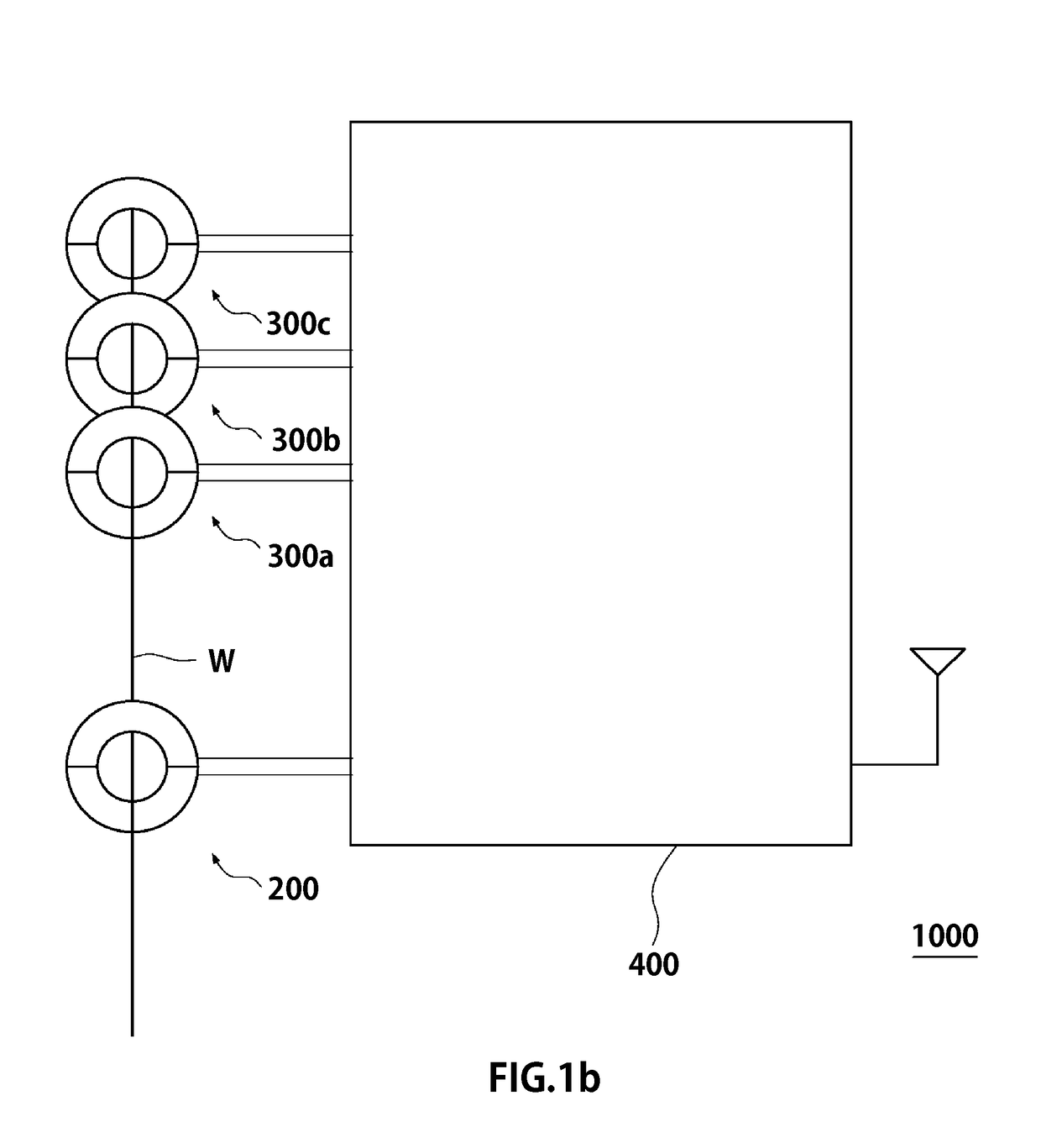
[0024]In the following, exemplary embodiments of a current transformer (CT) system 1000 in which a sensor CT and a generator CT according to the present disclosure having the above-described configuration are installed in para...


PUM

PropertyMeasurementUnit
distanceaaaaaaaaaa
poweraaaaaaaaaa
currentaaaaaaaaaa

Abstract

A current transformer system according to the present invention includes: a sensor CT detachably attached to an electric power transmission / distribution line for detecting the current flowing through the power line by means of electromagnetic induction; a generator CT detachably attached to an electric power transmission / distribution line for generating power by means of electromagnetic induction; and a microprocessor for controlling the sensor CT and the generator CT. According to the present invention, the generator CT is used as the main power source so as to perform independently power supply and facilitate the construction of an additional source in need of additional power.

Description

RELATED APPLICATIONS[0001]This application is the U.S. National Phase of and claims priority to International Patent Application No. PCT / KR2014 / 001374, International Filing Date Feb. 20, 2014, entitled Current Transformer System With Sensor CT And Generator CT Separately Arranged In Parallel In Electric Power Line, And Integrated System For Controlling Same In Wireless Communications Network (as translated), which claims benefit of Korean Application No. KR10-2013-0018739, filed Feb. 21, 2013 entitled Current Transformer System Including Structure Of Sensor CT And Structure Of Generator CT Mounted In Parallel On Electric Power Line, And Integrated Wireless Communication System Monitoring The Same (as translated); and Korean Application No. 10-2013-0053188, filed May 10, 2013 entitled Current Transformer (as translated); all of which are incorporated herein by reference in their entireties.TECHNICAL FIELD[0002]The present disclosure relates to a current transformer (CT) system in whi...

Claims


Application Information

Patent Timeline
Patent Type & Authority Patents(United States)
IPC IPC(8): H01F27/42H01F38/20H04W4/00H01F38/16H02J7/00H01F27/02H04B5/00G01R31/02H01F38/14H04W4/80G01R15/18H04W84/12
CPCH01F27/427G01R15/183G01R15/186G01R31/027H01F27/02H01F38/14H01F38/20H02J7/0068H04B5/0043H04B5/0075H04W4/80H01F38/16H04W84/12H04B5/73H04B5/24G01R31/62
Inventor KOO, JA-ILKIM, TAE-KYOUNG
Owner FERRARIS INC
Learn More