
Bearing raceway and a method of manufacturing a bearing

a technology of bearings and raceways, which is applied in the direction of bearing rigid support, machines/engines, mechanical equipment, etc., can solve the problems of cage pocket wear and bearing failure, increased contact stress, and mechanical instability,

Active Publication Date: 2019-02-05
ROLLS ROYCE PLC
View PDF12 Cites 1 Cited by
  • Summary
  • Abstract
  • Description
  • Claims
  • Application Information

AI Technical Summary

Benefits of technology

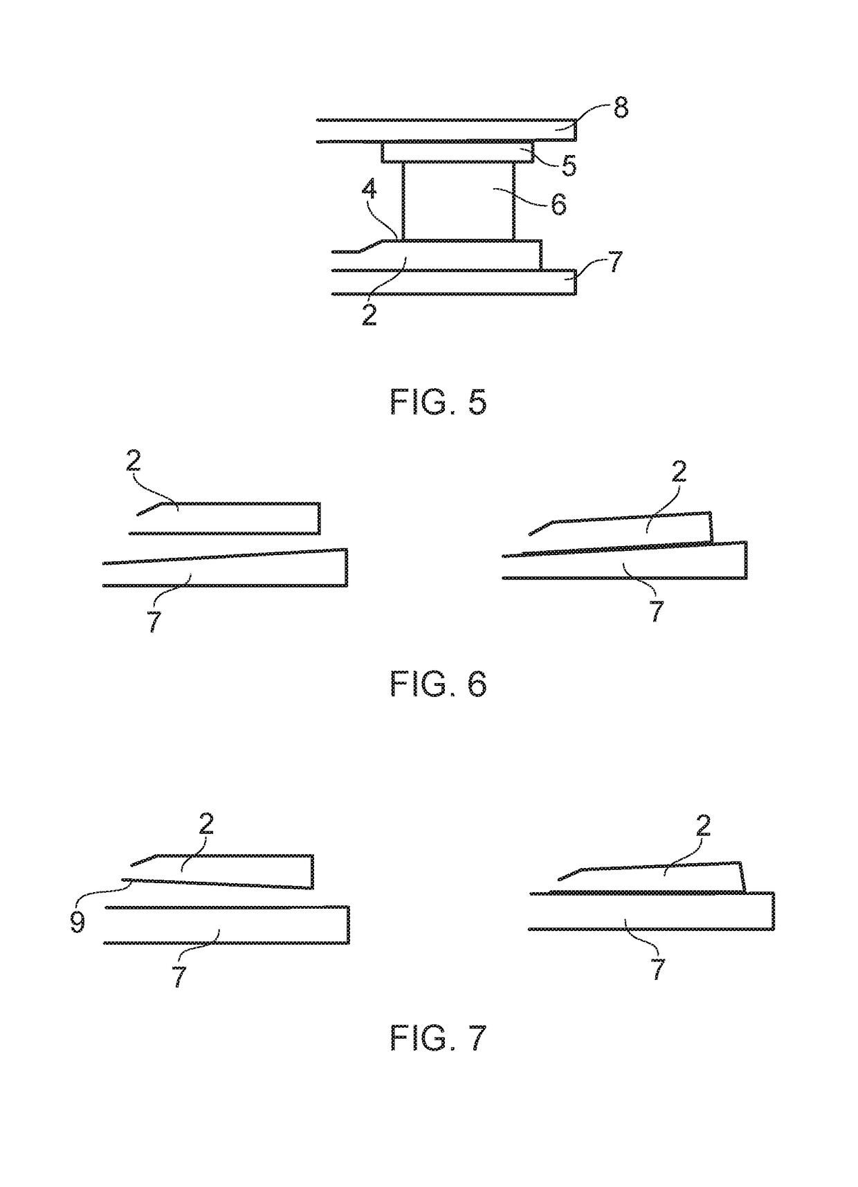
[0012]Providing a bearing with an inner or outer race with a taper angle allows the operational induced deformations to be more readily accommodated by the bearing with reduced overall wear.
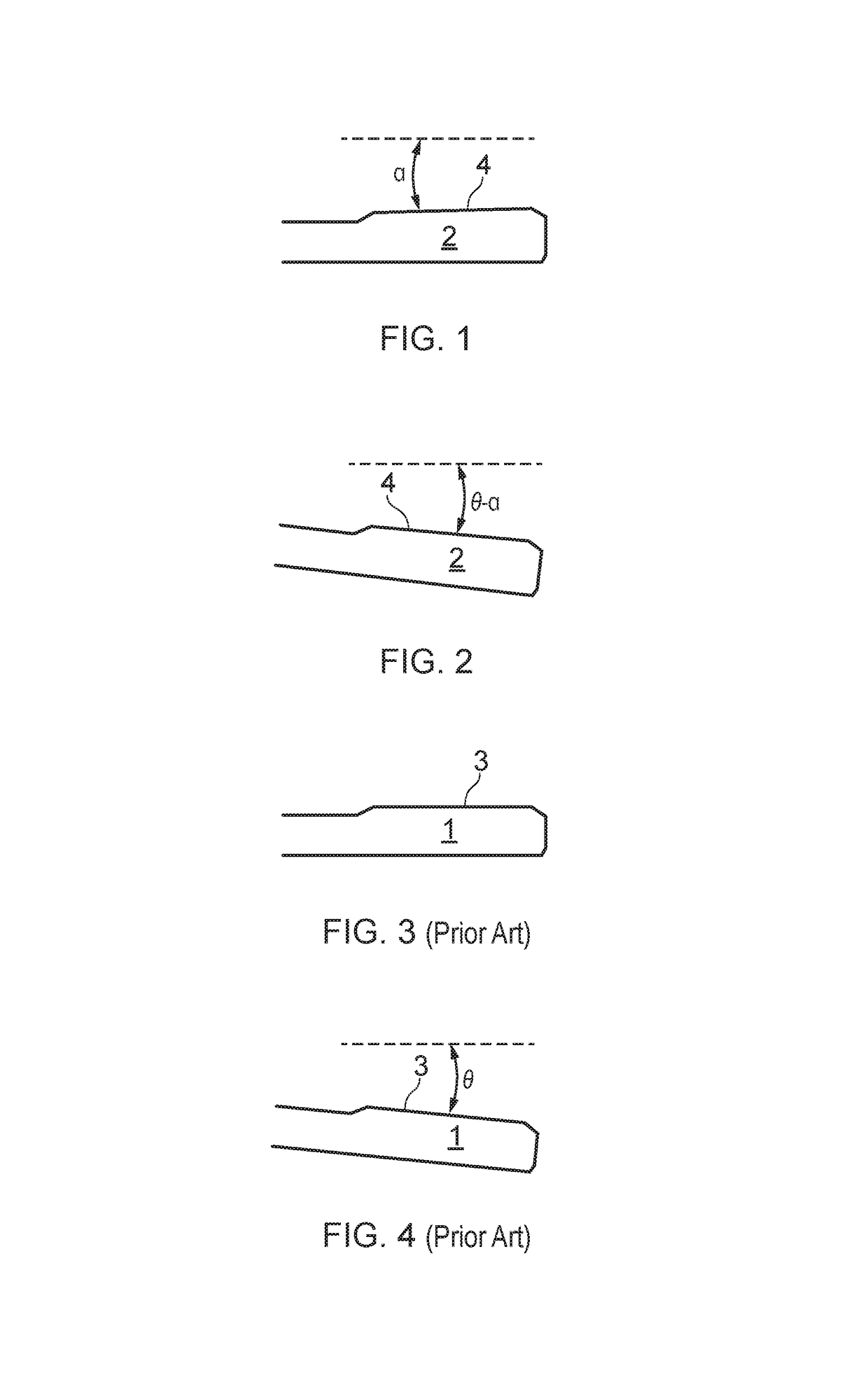
[0023]Another aspect of the disclosure provides a component for a bearing, the component comprising a bearing surface, wherein the bearing surface is formed so as to be tapered at rest, thereby offsetting deformation of the bearing during an operational condition which generates an induced angle in the bearing surface or an opposing surface of the bearing.

Problems solved by technology

If the raceway is not perpendicular to the roller this can lead to a skewed contact profile which can cause increased contact stress, dynamic instability, cage pocket wear and bearing failure.
Misalignment of a roller bearing can be caused through manufactured geometric tolerances, eccentricity of installation in to a rotor system, and operational conditions.
If it is not possible to ensure the bearing is operating within reliable levels of misalignment by addressing any of these issues then the bearing is likely to become distressed.

Method used


Image

  • Bearing raceway and a method of manufacturing a bearing
  • Bearing raceway and a method of manufacturing a bearing
  • Bearing raceway and a method of manufacturing a bearing

Examples


Embodiment Construction

[0045]FIGS. 1 and 5 show a bearing race 2 (component) of a roller bearing. The bearing race 2 is annular and is arranged concentrically with a further bearing race 5 having a different diameter to that of the bearing race 2 to form inner and outer races. Rollers 6, which may be cylindrical, are disposed between the inner and outer races of the bearing to permit relative rotation between the inner and outer races. The inner and outer races are mounted on to or within a supporting structure such as a housing 7, or a shaft 8. It will be appreciated that the bearing arrangement may also include other parts such as a bearing cage or the like,

[0046]The bearing race 2 comprises a raceway 4 (bearing surface) which contacts the rollers. The raceway 4 is therefore either an inner surface of the outer race or an outer surface of the inner race.

[0047]The raceway 4 is tapered at an angle α such that the raceway 4 is inclined toward an axis of rotation of the bearing race 2 when at rest, as is sh...


PUM


Abstract

A component 2 for a bearing, the component 2 comprising a bearing surface 4, wherein the bearing surface 4 is formed so as to be tapered at rest, thereby offsetting deformation of the bearing during an operational condition which generates an induced angle in the bearing surface 4 or an opposing surface of the bearing. A method of manufacturing a bearing is also provided. The method comprises: determining an induced angle of a component 2 of the bearing caused by deformation of the bearing during an operational condition: and providing a surface 4 of the component 2 or an opposing component with a taper at rest so as to offset the induced angle generated during the operational condition.

Description

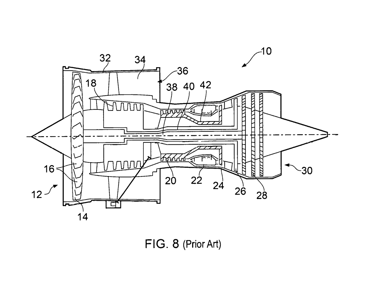
TECHNICAL FIELD OF INVENTION[0001]The invention relates to a bearing raceway and a method of manufacturing a bearing.BACKGROUND OF INVENTION[0002]FIG. 8 shows a ducted fan gas turbine engine 10 comprising in axial flow series: an air intake 12, a propulsive fan 14 having a plurality of fan blades 16, an intermediate pressure compressor 18, a high-pressure compressor 20, a combustor 22, a high-pressure turbine 24, an intermediate pressure turbine 26, a low-pressure turbine 28 and a core exhaust nozzle 30. A nacelle (not shown) generally surrounds the fan casing 32 and engine 10 and defines the intake 12, a bypass duct 34 and a bypass exhaust nozzle. The engine has a principal axis of rotation 31.[0003]Air entering the intake 12 is accelerated by the fan 14 to produce a bypass flow and a core flow. The bypass flow travels down the bypass duct 34 and exits the bypass exhaust nozzle 36 to provide the majority of the propulsive thrust produced by the engine 10. The core flow enters in ax...

Claims


Application Information

Patent Timeline
Patent Type & Authority Patents(United States)
IPC IPC(8): F02C7/06F16C19/52F16C23/08F01D25/16
CPCF02C7/06F01D25/16F16C23/08F16C19/52F16C2360/23F05D2240/50F16C35/067F16C19/30F16C33/585F16C33/64F05D2230/64F05D2250/292F16C2240/34F01D25/164F16C33/58
Inventor ASHMORE, DAREN R.PLANT, JAMES A.
Owner ROLLS ROYCE PLC
Learn More