
Systems, devices, and methods for orienting an antenna mast

a technology for installing and aligning antennas, which is applied in the direction of antennas, antenna details, electrical equipment, etc., can solve the problems of increasing the time and effort required for aligning an antenna mounted on a non-aligned mast, poor orientation of the mast, and even poor alignment of the antenna, so as to increase the ease of installation and alignment. , the effect of quick and easy installation

Active Publication Date: 2019-02-05
DISH TECH L L C
View PDF13 Cites 0 Cited by
  • Summary
  • Abstract
  • Description
  • Claims
  • Application Information

AI Technical Summary

Benefits of technology

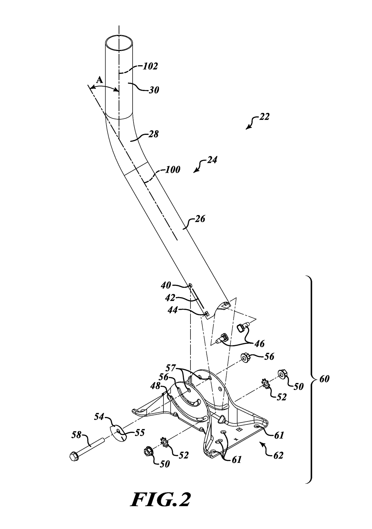
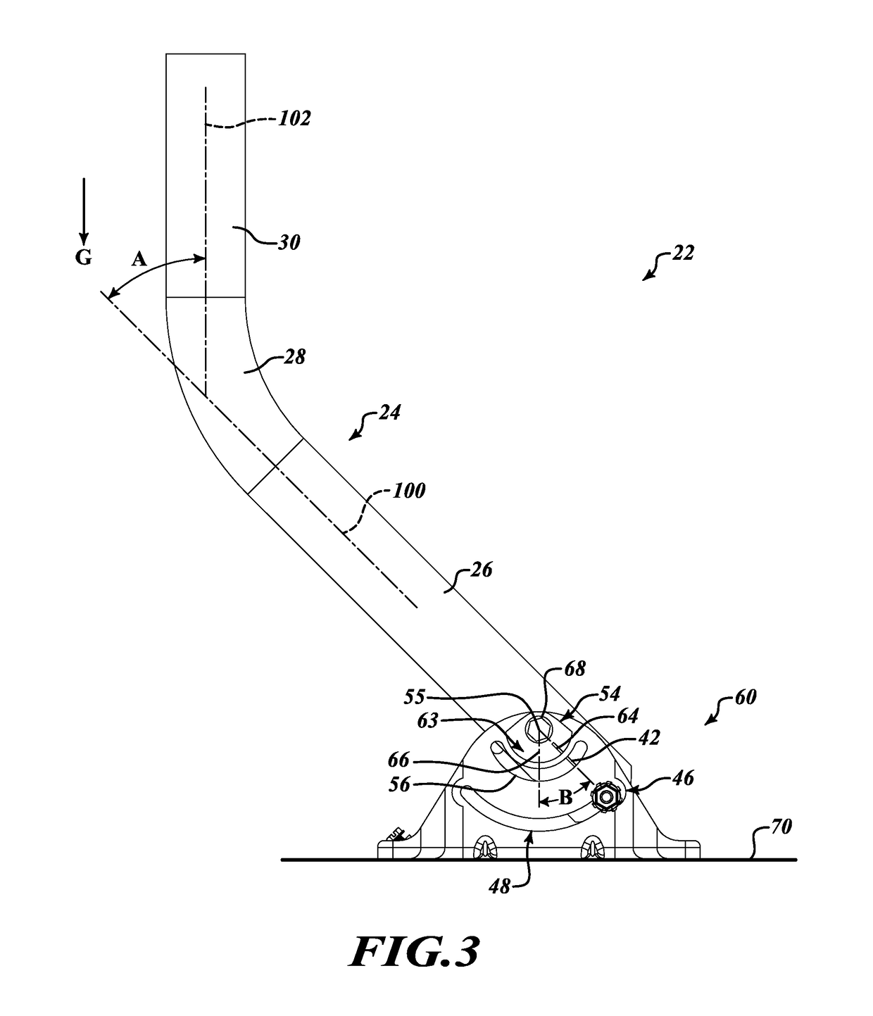
The patent text describes an antenna mast assembly with a plumb indicator near its lower end, which makes it easier to quickly and accurately align the mast and the subsequent alignment of an antenna attached to the mast. The assembly also includes a foot that is connected to the mast and helps to align its upper end in a vertical orientation. The technical effects of this invention are increased speed and accuracy in aligning antenna masts, particularly mast assemblies with bent or angled masts.

Problems solved by technology

The top and bottom of the mast may be separated by several feet and difficulty in assuring proper orientation of the top of the mast while attaching the foot of the mast to a structure has caused many installers to simply use their eyes to estimate the correct orientation of the antenna while attaching the foot to the structure, rather than use a level.
Eyeballing the mast orientation can result in poorly orientated masts and in added difficulty in attaching and aligning antennas and even poorly aligned antennas.
Aligning an antenna mounted on a non-aligned mast is more time consuming than aligning an antenna mounted on an aligned mast.
This extra time results an installer installing fewer installations each day.
Poorly aligned antennas are also more susceptible to signal degradation and loss and can result in decreased customer satisfaction.

Method used


Image

  • Systems, devices, and methods for orienting an antenna mast
  • Systems, devices, and methods for orienting an antenna mast
  • Systems, devices, and methods for orienting an antenna mast

Examples


Embodiment Construction

[0020]In the following description, certain specific details are set forth in order to provide a thorough understanding of various disclosed embodiments. However, one skilled in the relevant art will recognize that embodiments may be practiced without one or more of these specific details, or with other methods, components, materials, etc. In other instances, well-known structures associated with antenna masts, satellite communication receiving systems, and methods of their orientation have not been shown or described in detail to avoid unnecessarily obscuring descriptions of the embodiments.

[0021]Unless the context requires otherwise, throughout the specification and claims that follow, the word “comprise” and variations thereof, such as, “comprises” and “comprising” are to be construed in an open, inclusive sense, that is, as “including, but not limited to.”

[0022]References throughout this specification to “one embodiment” or “an embodiment” means that a particular feature, struct...


PUM


Abstract

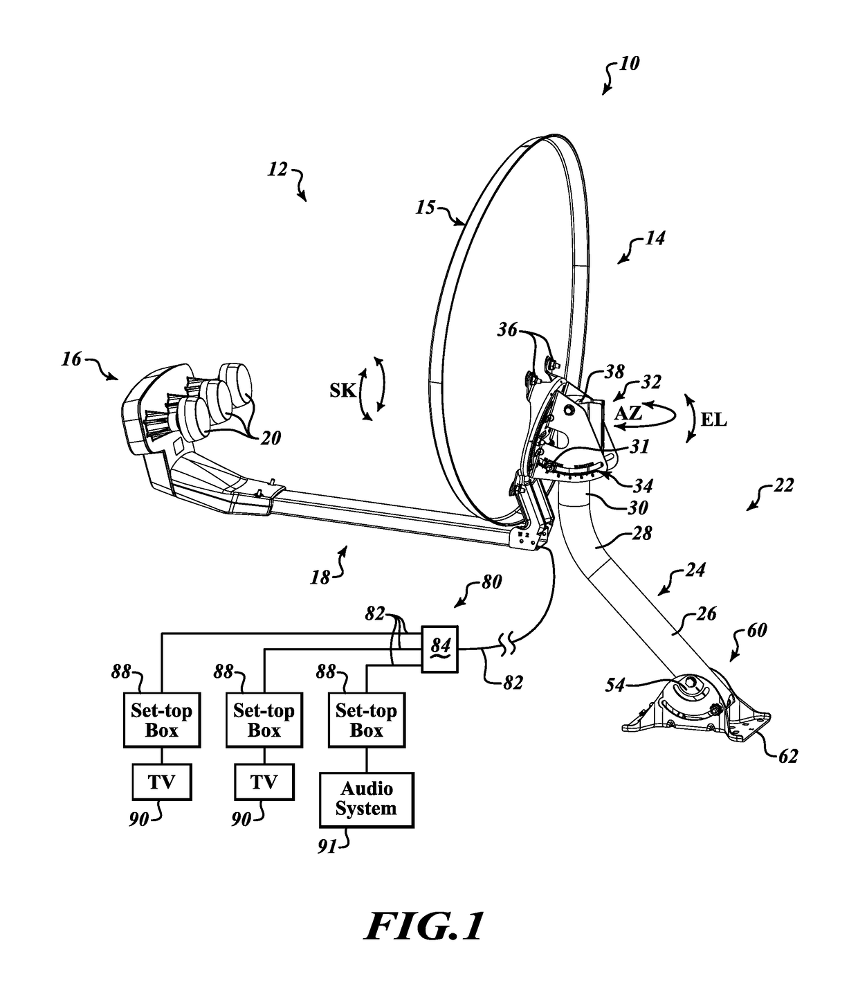
An antenna mast assembly with an alignment plumb is provided which allows for increased speed and accuracy in aligning antenna masts. The antenna mast assembly includes an antenna mast. An upper end of the mast extends in a first direction and a lower end of the mast extends in a second direction with an angle between the first and second directions. The bend in the mast creates the angle between the upper and lower ends. The upper end of the mast is connected to an antenna. The mast also includes an orientation indicator near its lower end and aligned with the first direction. The mast assembly also includes a foot configured to couple the lower end of the mast to a mounting surface and a plumb coupled to the foot. The plumb includes a plumb indicator that aligns with the mast orientation indicator and indicates that the upper end of the mast is orientated vertically.

Description

BACKGROUND[0001]Technical Field[0002]The present disclosure generally relates to antenna assemblies and methods for installing and aligning antenna assemblies.[0003]Description of the Related Art[0004]Radio antennas, and in particular directional radio antennas such as satellite dish antennas, are oriented and positioned for optimal reception and transmission of radio signals. Satellite dishes are often installed on a mast. The mast may be oriented vertically with respect to the ground. A satellite dish mast, in particular those used in residential installations, for example, those used in Ku band direct-broadcast satellite television systems, include a bent mast with a satellite dish attached to one end of the mast and a mounting foot attached to the other end. During installation an installer may orient the top of the mast so that it is vertical with respect to the ground. Vertically aligning the top of the mast makes installing and aligning an antenna easier.[0005]An installer us...

Claims


Application Information

Patent Timeline
Patent Type & Authority Patents(United States)
IPC IPC(8): H01Q1/12H01Q3/06F16L3/205F16L3/16
CPCH01Q1/125H01Q3/06F16L3/2053F16L3/16
Inventor BAILEY, MATTHEWROBERTS, WILLIAM
Owner DISH TECH L L C
Learn More