Single phase brushless motor and power tool utilizing same

a single-phase brushless motor and power tool technology, applied in the field of motors, can solve the problems of restricted use of single-phase motors in applications requiring large startup torque, such as power tools, and achieve the effect of increasing the startup torque of the motor and large peak value of cogging torqu

Inactive Publication Date: 2019-02-05
JOHNSON ELECTRIC SA
View PDF6 Cites 35 Cited by
  • Summary
  • Abstract
  • Description
  • Claims
  • Application Information

AI Technical Summary

Benefits of technology

[0023]When compared with the prior art, the present invention has the following advantages: the present invention can produce a large peak value of the cogging torque, which prevents the rotor from stopping at the dead point position and increases the startup torque of the motor.

Problems solved by technology

However, because of its poor startup capability, the use of the single phase motor in applications requiring large startup torque, such as in power tools, has been restricted.

Method used


Image

  • Single phase brushless motor and power tool utilizing same
  • Single phase brushless motor and power tool utilizing same
  • Single phase brushless motor and power tool utilizing same

Examples


first embodiment

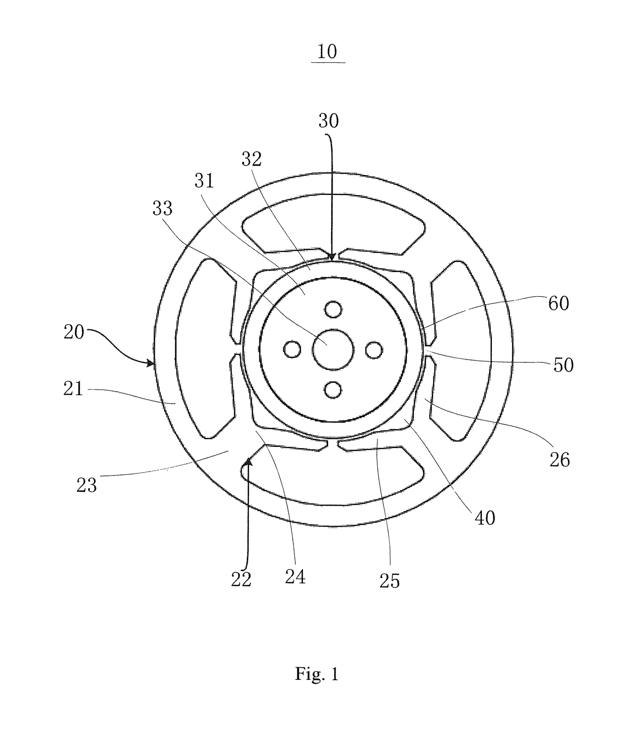
[0034]Referring to FIG. 1, a single phase brushless motor 10 in accordance with a first embodiment of the present invention includes a stator 20 and a rotor 30 rotatable relative to the stator 20.

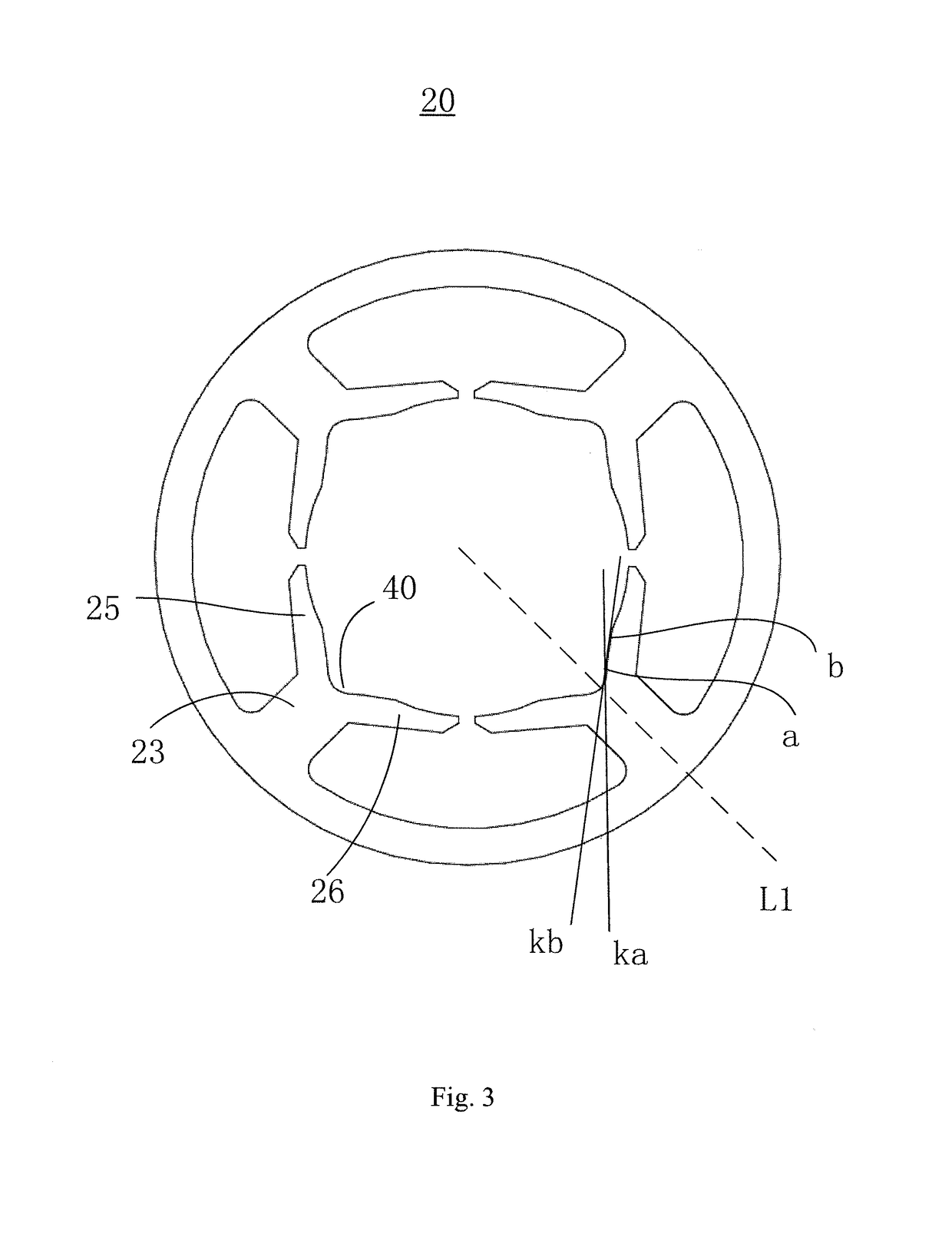
[0035]The stator 20 includes a stator core made of a magnetic-conductive soft magnetic material such as silicon steel, and windings 28 (see FIG. 5) wound around the stator core. The stator core includes a yoke 21 and at least two teeth 22 extending inward from the yoke 21. The tooth 22 includes a tooth body 23 and a tooth tip 24 formed at a distal end of the tooth body 23. The windings 28 may be wound around the tooth body 23. The tooth tip 24 includes two pole shoes 25, 26 extending to two sides of the tooth, respectively. The rotor 30 is received in a space defined between the pole shoes 25, 26 of the at least two teeth 22. The two pole shoes 25, 26 of each tooth 22 are symmetrical about a radial center line of the tooth body 23 of the corresponding tooth 22, i.e. pole faces of the two po...

second embodiment

[0045]Referring to FIG. 6, different from the first embodiment, the cross section of the positioning groove 40 is arc-shaped.

[0046]In this embodiment, the circumferential width of the positioning groove 40 is equal to the circumferential width of the tooth body 23 of the tooth 22. In an alternative embodiment, the circumferential width of the positioning groove 40 is greater than or less than the circumferential width of the tooth body 23 of the tooth 22.

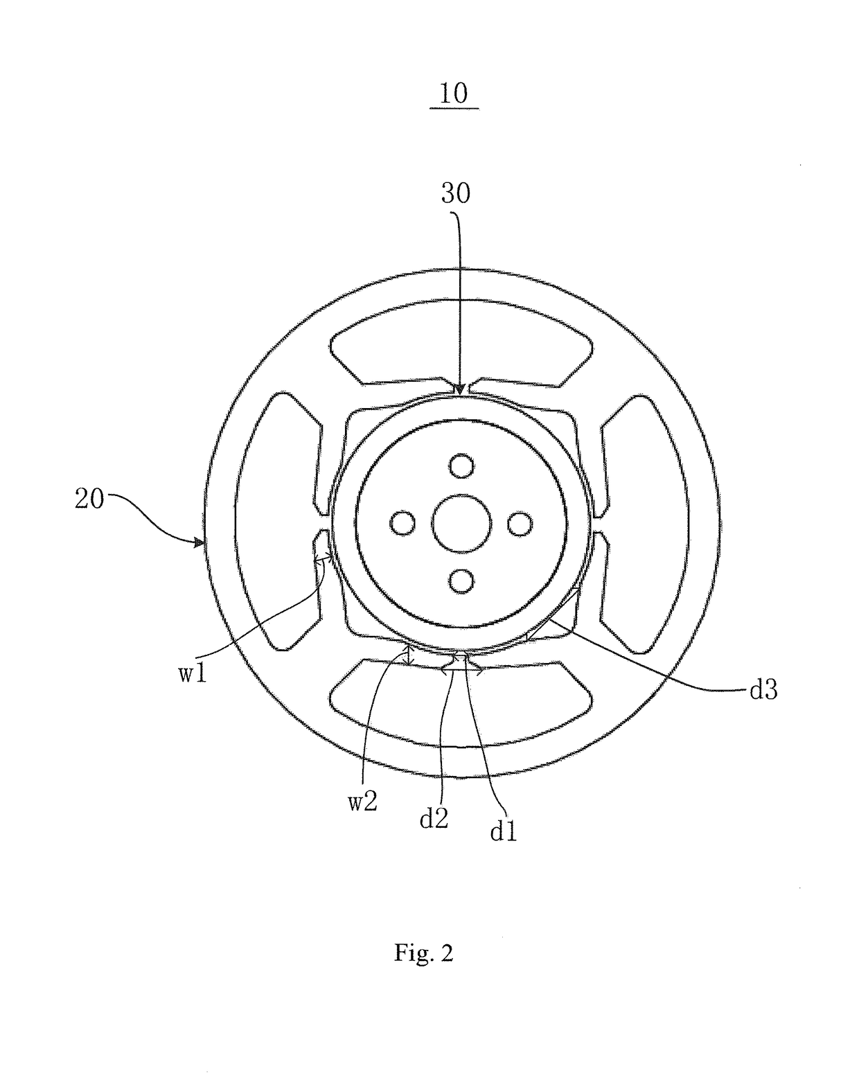
[0047]A slot opening 50 is formed between two adjacent pole shoes of the at least two different teeth 22. In this embodiment, the slot opening 50 has a rectangular-shaped cross section. The circumferential width of the positioning groove 40 is greater than the circumferential width of the slot opening 50. Preferably, the circumferential width of the slot opening 50 is greater than 2 mm and, more preferably, greater than 2.5 mm.

[0048]Referring to FIG. 7, the circumferential width of the slot opening 50 is indicated by d4, and the cir...

third embodiment

[0051]Referring to FIG. 9 and FIG. 10, in this embodiment, the rotor 30 includes a rotary shaft 33, a rotor core 31 fixedly mounted around the rotary shaft 33, and a plurality of permanent magnets 32 mounted to an outer circumference of the rotor core 31. Each permanent magnet 32 forms one permanent magnetic pole at the outer circumference of the rotor 30. In this embodiment, the number of the permanent magnetic poles is the same as the number of the teeth 22, which is six. The rotor magnetic core 31 is a cylindrical body. Each permanent magnet 32 has a thickness b gradually decreasing from a circumferential center to two sides thereof. Therefore, the outer radius R of the rotor 30 gradually decreases from the center to two sides of each permanent magnetic pole.

[0052]In this embodiment, pole faces of the two pole shoes 25, 26 of each tooth 22 are located on a same cylindrical surface, except for an area of the positioning groove 40. When the rotor 30 stops, a part of the permanent m...


PUM


Abstract

A single phase brushless motor and a power tool are provided. The single phase brushless motor includes a stator and a rotor. The stator includes a stator core and windings wound around the stator core. The stator core includes a yoke and at least two teeth. The tooth includes a tooth body and a tooth tip. The tooth tip includes first and second pole shoes. The two pole shoes of each tooth are symmetrical about a center line of the tooth body. Each tooth defines a positioning groove facing the rotor between the two pole shoes. Pole shoes of adjacent two of the at least two teeth are spaced apart by a slot opening. A width of the positioning groove is greater than a width of the slot opening. The peak value of the cogging torque of the motor is increased, and the motor has a large startup torque.

Description

CROSS REFERENCE TO RELATED APPLICATIONS[0001]This non-provisional patent application claims priority under 35 U.S.C. § 119(a) from Patent Application No. 201510552087.8 filed in The People's Republic of China on Sep. 1, 2015, and Patent Application No. 201610214432.1 filed in The People's Republic of China on Apr. 7, 2016.FIELD OF THE INVENTION[0002]The invention relates to motors, and in particular to a single phase brushless motor and a power tool utilizing the single phase brushless motor.BACKGROUND OF THE INVENTION[0003]Single phase motors have the advantage of low cost. However, because of its poor startup capability, the use of the single phase motor in applications requiring large startup torque, such as in power tools, has been restricted. Therefore, a single phase brushless motor with strong startup capability is urgently desired.SUMMARY OF THE INVENTION[0004]Thus, there is a desire for a single phase brushless motor which can overcome the above shortcomings.[0005]In one as...

Claims


Application Information

Patent Timeline
Patent Type & Authority Patents(United States)
IPC IPC(8): H02K29/03H02K1/14H02K7/14H02K21/16H02K1/27
CPCH02K1/146H02K1/276H02K1/278H02K7/145H02K21/16H02K29/03H02K1/2726H02K2213/03
Inventor LI, YUEZHANG, TAOZHOU, CHUI YOUCHAI, JIECHU, JUN JIEZUO, XIAO BINGWANG, YONGLI, YONG
Owner JOHNSON ELECTRIC SA
Why Eureka
Try Eureka