Resolver excitation apparatus

a technology of excitation apparatus and excitation circuit, which is applied in the direction of electrical/magnetically converting sensor output, measurement devices, instruments, etc., can solve the problems of increasing loss, affecting the detection accuracy of magnetic pole position, and not being practicably easy to flexibly. , to achieve the effect of stabilizing the amplitude of excitation signal, increasing radiation noise, and reducing detection accuracy

Active Publication Date: 2018-01-30
AISIN AW CO LTD
View PDF16 Cites 1 Cited by
  • Summary
  • Abstract
  • Description
  • Claims
  • Application Information

AI Technical Summary

Benefits of technology

[0009]As described above, a parallel resonant circuit is effective in reducing loss of the resolver excitation apparatus. In order to obtain amplitude required to excite the excitation winding, the amplitude of the excitation signal needs to be increased. In order to increase the amplitude of the excitation signal, however, a power supply voltage having a voltage range larger than a peak value of the excitation signal is required, and thus the resolver excitation apparatus cannot be flexibly applied to a wide range of the power supply voltage. Moreover, the higher the power supply voltage is, the greater the loss is. On the other hand, a series resonant circuit is capable of outputting the excitation signal having a peak value larger than the voltage range of the power supply voltage. In order to suppress the loss of the circuit, the power supply voltage need be optimized, and thus the resolver excitation apparatus cannot be flexibly applied to a wide range of the power supply voltage. When the resolver excitation apparatus includes the parallel resonant circuit and the series resonant circuit as in the above characteristic configuration, it is possible to generate the excitation signal having predetermined amplitude by combining characteristics of the series resonant circuit with, e.g., an amplifier, and to reduce the loss of the circuit by using the function of the parallel resonant circuit. That is, according to this characteristic configuration, the resolver excitation apparatus can be provided which can be flexibly applied to a wide power supply voltage range, and which can apply a sinusoidal excitation signal having amplitude required for excitation to the excitation winding of the resolver by using a low-loss circuit configuration.
[0011]There are a plurality of possible combinations of the parallel resonant circuit and the series resonant circuit. In one form, in the resolver excitation apparatus according to the present invention, it is preferable that the series resonant element be connected to a parallel circuit of the parallel resonant element and the excitation winding. In this circuit configuration, an equivalent circuit of the parallel resonant circuit, the series resonant circuit, and the exciting winding is relatively simple, and circuit constants of the parallel resonant circuit and the series resonant circuit can be obtained by relatively simple computation. Specifically, in this resolver excitement apparatus, it is preferable that the circuit constant of the parallel resonant element be set according to a ratio of the amplitude of the excitation source signal to that of the excitation signal, and the circuit constant of the series resonant element be set so that a reactance component of load impedance as synthetic impedance of the excitation winding, the parallel resonant element, and the series resonant element is equal to zero.
[0013]The excitation source signal is generated by, e.g., outputting a discrete voltage value while the value is varied in a time series manner. That is, the excitation source signal sometimes has a stair-like waveform. In such a signal having a stair-like waveform, a signal having a frequency component (high frequency component) much higher than a fundamental component has been superimposed. Detection accuracy of the position of a magnetic pole may be decreased if this high frequency component remains in the excitation signal. Moreover, the high frequency component may increase radiation noise (emission noise). It is therefore desirable that such a high frequency component be reduced by the time the excitation source signal is output as the excitation signal. For example, it is preferable to add a noise filter to the circuit to attenuate the high frequency component. In one form, it is preferable that the resolver excitation apparatus according to the present invention further include: a feedback controller having an excitation source signal input line to which the excitation source signal is applied, and a feedback loop that feeds the excitation signal back to the excitation source signal input line, and performing feedback control to stabilize the amplitude of the excitation signal; and a band-pass filter that is placed in a preceding stage to a feedback point where the excitation signal is fed back, and that filters the excitation source signal.

Problems solved by technology

Accordingly, it is not practically easy to flexibly and appropriately set the frequency of the excitation signal as in Patent Document 1.
However, loss of the circuit tends to increase with an increase in power supply voltage.
The loss is small if the excitation apparatus includes a power supply having a power supply voltage value optimal for the excitation apparatus, but otherwise the loss may increase.
For example, if the voltage value of the power supply included in the excitation apparatus is higher than the optimal power supply voltage value, the loss is greater as the power supply voltage value is higher.
If the voltage value of the power supply included in the excitation apparatus is lower than the optimal power supply voltage value, the excitation apparatus cannot provide a sinusoidal output having required amplitude, and provides an output having a waveform distorted with respect to the sinusoidal waveform.

Method used


Image

  • Resolver excitation apparatus
  • Resolver excitation apparatus
  • Resolver excitation apparatus

Examples


Embodiment Construction

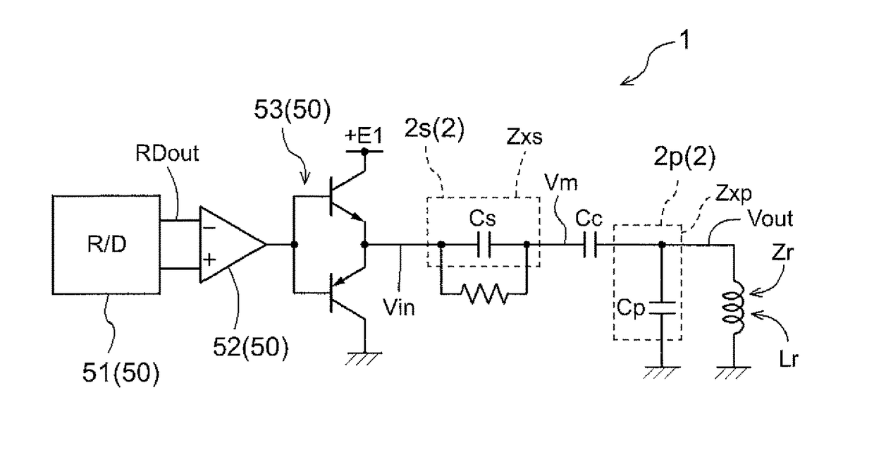
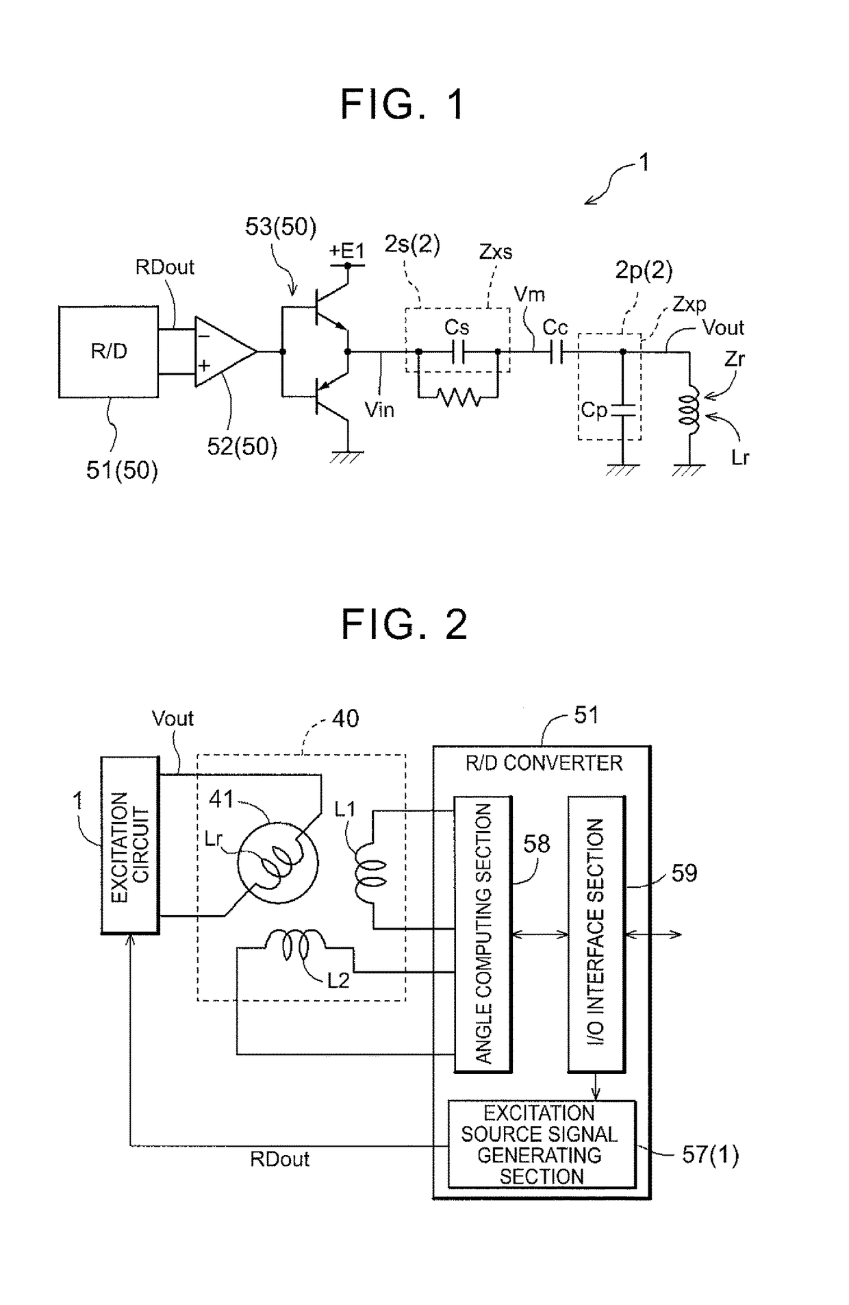
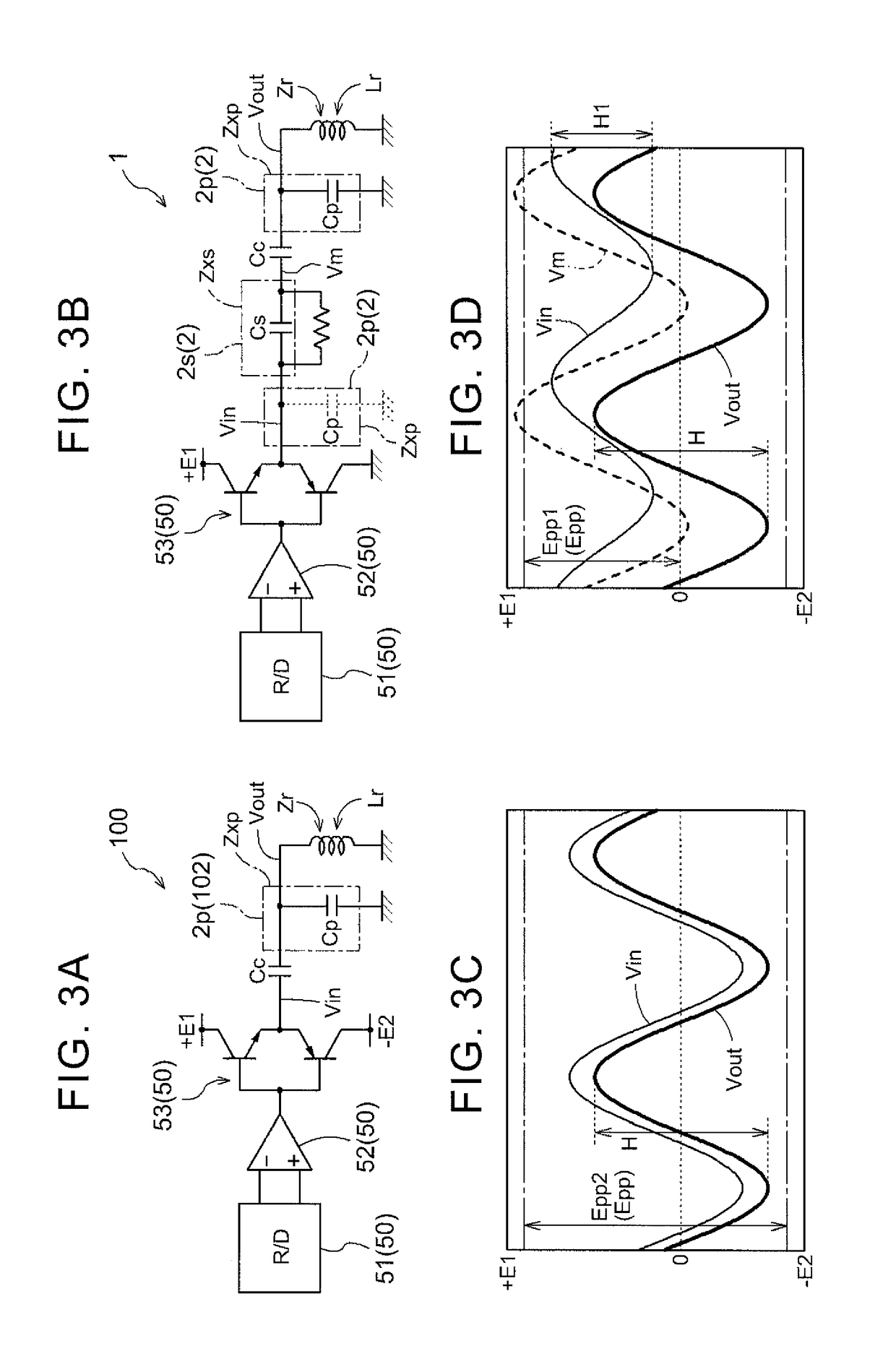
[0061]Excitation circuits that are applied to a resolver excitation apparatus according to the present invention are shown by way of example with reference to the accompanying drawings to describe embodiments of the present invention. The schematic circuit diagram of FIG. 1 shows an excitation circuit 1 illustrating the subject matter of the present invention. The block diagram of FIG. 2 shows the relation among the excitation circuit 1, a resolver 40, and a resolver / digital converter (RID converter) 51 described below. In order to excite an excitation winding Lr of the resolver 40, the excitation circuit 1 (resolver excitation apparatus) adjusts the amplitude of a sinusoidal excitation source signal RDout to generate an excitation signal Vout having predetermined amplitude (e.g., corresponding to one half of a peak value “H” shown in FIG. 3). This excitation circuit 1 has: an excitation source signal supply section 50 having the RID converter 51 that outputs the excitation source s...


PUM


Abstract

A resolver excitation apparatus that adjusts amplitude of a sinusoidal excitation source signal to generate an excitation signal having predetermined amplitude in order to excite an exciting winding of a resolver. A parallel resonant circuit having a parallel resonant element that functions as parallel resonant impedance for impedance of the excitation winding. A series resonant circuit having a series resonant element that functions as series resonant impedance for the impedance of the excitation winding.

Description

TECHNICAL FIELD[0001]The present invention relates to resolver excitation apparatuses that adjust the amplitude of a sinusoidal excitation source signal to generate an excitation signal having a predetermined amplitude in order to excite an excitation winding of a resolver.BACKGROUND ART[0002]Resolvers are sometimes used as a rotation detection sensor that detects rotation (the rotational speed or rotational position (angle of rotation) of a rotor) of a rotating electrical machine. The resolvers typically have an excitation winding on the stator side, and detect rotation of the rotating electrical machine based on a principle that the angle of rotation of a rotor is detected according to an output voltage induced to an output winding provided on the rotor side. Accordingly, an alternating current (AC) signal is normally applied to the excitation winding. An excitation apparatus that applies this AC signal has a sinusoidal oscillator circuit that generates a sinusoidal oscillation si...

Claims


Application Information

Patent Timeline
Patent Type & Authority Patents(United States)
IPC IPC(8): G01D5/20
CPCG01D5/2073G01D5/20
Inventor NAKAMURA, YASUSHI
Owner AISIN AW CO LTD
Why Eureka
Try Eureka