
Apparatus for forming polymer, comprising polymer backflow prevention portion

a technology backflow prevention, which is applied in the field of polymer forming apparatus having a polymer backflow prevention unit, can solve the problems of clogging affecting the process, and preventing the flow of polymer resin back to the gas injection gate, so as to increase the surface area to volume ratio of polymer resin, prevent the flow of polymer resin, and reduce the effect of process loss

Active Publication Date: 2019-02-12
LG HAUSYS LTD
View PDF51 Cites 0 Cited by
  • Summary
  • Abstract
  • Description
  • Claims
  • Application Information

AI Technical Summary

Benefits of technology

The present invention is about preventing a thermoplastic polymer resin from flowing back into a foaming agent injection pipe during a physical foam forming process. This is achieved by adding backflow prevention holes which increase the surface area to volume ratio of the polymer resin and prevent it from flowing back. This results in higher viscosity of the polymer resin than the foaming gas, which prevents it from flowing back. The foaming gas, on the other hand, increases the surface area to volume ratio of gas through the backflow prevention holes, which helps it melt more quickly into the polymer resin. This results in more efficient production and reduced process loss.

Problems solved by technology

In this case, if an internal pressure of the barrel filled with the polymer resin is higher than injection pressure of the foaming gas, the polymer resin flows back to the gas injection gate and clogs the gas injection gate.
In this case, the process is delayed until repair of the gas injection gate is finished, and there can be loss of components in the apparatus.

Method used


Image

  • Apparatus for forming polymer, comprising polymer backflow prevention portion
  • Apparatus for forming polymer, comprising polymer backflow prevention portion
  • Apparatus for forming polymer, comprising polymer backflow prevention portion

Examples


Embodiment Construction

[0080]Next, operation of a plastic forming apparatus with the foregoing structure will be described.

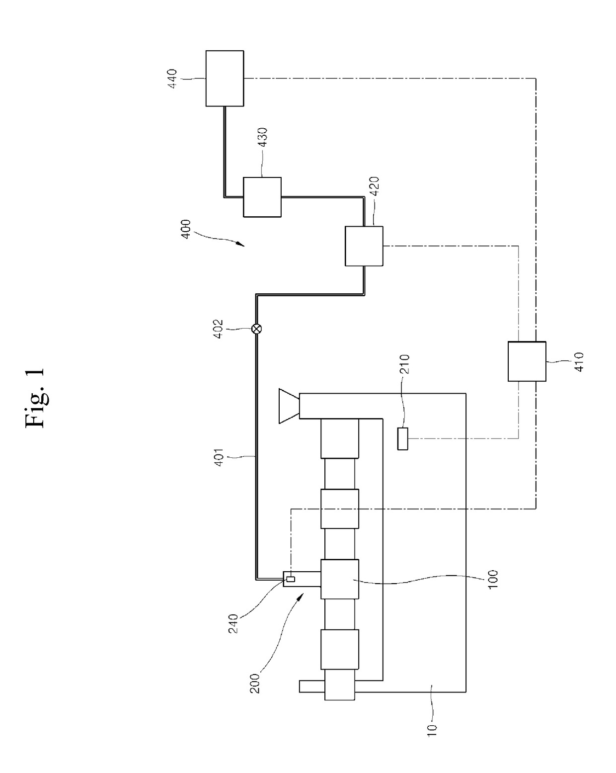
[0081]Referring to FIG. 1, the controller 410 uses the pump 420 to force a foaming agent stored in the foaming agent storage 440 to flow along the foaming agent supply line 401. In this case, the controller 410 opens the valve 402.

[0082]Herein, foaming gas will be described as an example of the foaming agent.

[0083]Thus, the foaming gas flows along the foaming agent supply line 401 and is then supplied to the foaming agent injection pipe 210.

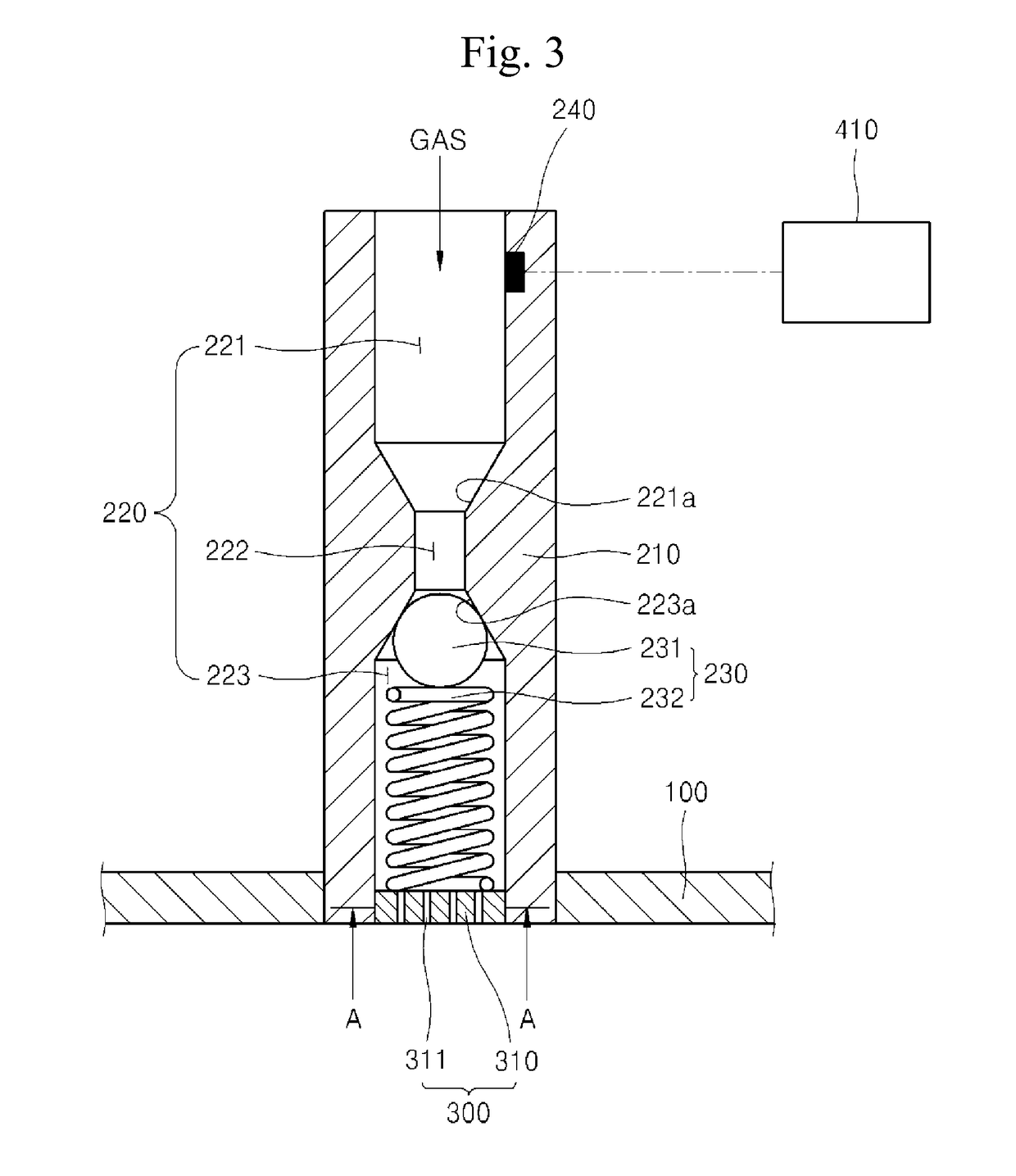
[0084]Referring to FIG. 3, the foaming gas is introduced into the inlet channel 221. At this time, the first pressure sensor 240 senses the pressure of the foaming gas injected into the channel 220 and transmits the sensed pressure to the controller 410.

[0085]Then, the foaming gas applies a predetermined pressure to the shut-off ball 231 while entering the middle channel 222, and the shut-off ball 231 is pressed down to thereby compress the elastic...


PUM

PropertyMeasurementUnit
pressureaaaaaaaaaa
inner diameteraaaaaaaaaa
surface areaaaaaaaaaaa

Abstract

The present invention provides an apparatus for forming a polymer, comprising: a chamber having a predetermined pressure and storing a molten polymer resin; a foaming agent injection portion connected to the chamber and supplying a foaming agent, which is supplied from the outside, into the chamber by forming a pressure equal to or higher than the pressure inside the chamber; and a polymer backflow prevention portion provided at the foaming agent injection portion, and through which the supplied foaming agent passes so as to increase a contact surface area with the polymer resin, thereby preventing the backflow of the polymer resin.

Description

TECHNICAL FIELD[0001]The present invention relates to a polymer forming apparatus having a polymer backflow prevention unit, and more particularly, to a polymer forming apparatus which has a polymer backflow prevention unit to efficiently prevent backflow of a molten polymer material toward a foaming agent injection gate.BACKGROUND ART[0002]In general, polymer forming technologies are used to manufacture various plastic products by melting polymer grains, i.e. pellets, with electric heat and mechanical friction and then extruding the molten polymer pellets into a mold or dies having a desired shape. Since material costs account for a very high percentage of total costs, foaming technologies have been developed in order to reduce material cost and decrease the weight of a polymer product.[0003]Foaming technologies form a lot of minute bubbles in a polymer product, in which a foaming agent is chemically or physically mixed with a polymer material and heat or pressure is applied to the...

Claims


Application Information

Patent Timeline
Patent Type & Authority Patents(United States)
IPC IPC(8): B29C44/34B29C45/18
CPCB29C44/3446B29C45/1816B29C44/35B29C44/60B29C45/76B29C2945/76006B29C2945/76775
Inventor JEON, BYUNG JOOLEE, EUNG KEECHOI, CHUL JUNEKIM, MYEONG HEEKIM, JI MUNJI, SEUNG WOOK
Owner LG HAUSYS LTD
Learn More