
Illuminating device, display device, and portable electronic device

a technology of electronic devices and illumination devices, which is applied in the direction of fixed installation, lighting and heating equipment, instruments, etc., can solve the problems of difficult so as to minimize the unevenness of light intensity, reduce the size of the illuminating device, and minimize the intensity of the illuminating light

Active Publication Date: 2019-02-12
E INK CORPORATION
View PDF16 Cites 0 Cited by
  • Summary
  • Abstract
  • Description
  • Claims
  • Application Information

AI Technical Summary

Benefits of technology

This patent describes an illuminating device that emits light from one surface of a light guide plate with sufficient intensity even in the regions near the ends of the light receiving section. The device includes a light receiving section with multiple cylindrical lens surfaces that widen the angle of the emitted light, ensuring even intensity distribution. This design eliminates unevenness in intensity and allows for a smaller size of the illuminating device. It is advantageous when the light guide plate has a larger maximum width than the portion corresponding to the light receiving section.

Problems solved by technology

In display devices including a reflective display panel, an illuminating device called frontlight is employed, because transmitted light is unable to be utilized.
Accordingly, it is difficult to minimize the unevenness of the intensity distribution shown in FIG. 5E.
In particular, when a maximum width of the light guide plate, taken in a width direction orthogonal to the direction in which the light emitting element and the light receiving section oppose each other, is by far larger than a width of the portion corresponding to the light receiving section as shown in FIG. 5E, it is difficult to minimize the unevenness of the light intensity shown in FIG. 5E.

Method used


Image

  • Illuminating device, display device, and portable electronic device
  • Illuminating device, display device, and portable electronic device
  • Illuminating device, display device, and portable electronic device

Examples


Embodiment Construction

[0027]Hereafter, embodiments of the present invention will be described with reference to the drawings. In the drawings referred to in the following description, layers and components may be illustrated in different reduction scales, for the sake of visual clarity.

Configuration of Display Device

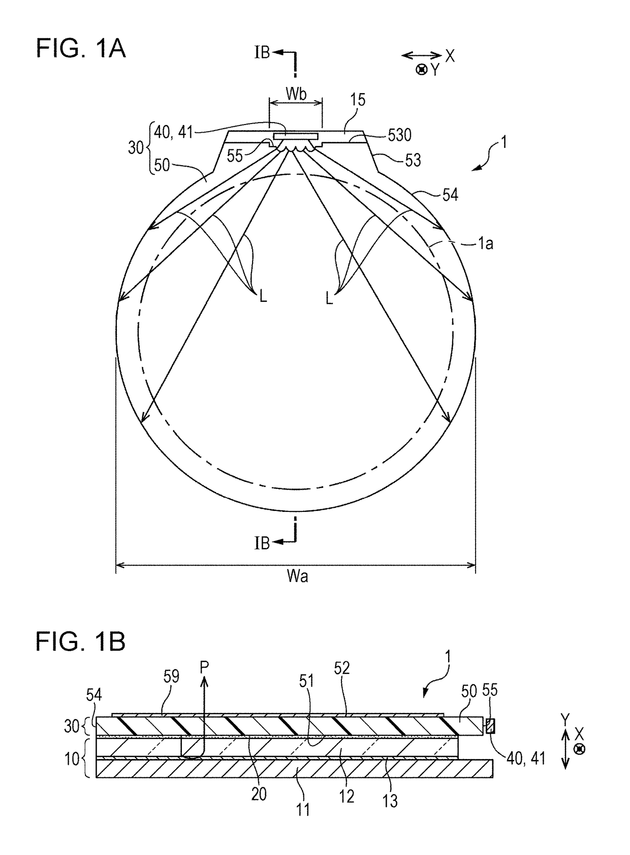
[0028]FIGS. 1A and 1B are schematic drawings for explaining a display device according to the present invention, FIG. 1A being a plan view of the display device, and FIG. 1B being a schematic cross-sectional view taken along a line IB-IB in FIG. 1A.

[0029]The display device 1 shown in FIG. 1 includes a display panel 10, and an illuminating device 30 including a light guide plate 50 opposed to the display panel 10.

[0030]In this embodiment, the display panel 10 is a reflective display panel such as an electrophoretic display panel, a reflective LCD panel, a MEMS element, or an optical interference element, and includes a first substrate 11, a light-transmissive second substrate 12 opposed to the...


PUM


Abstract

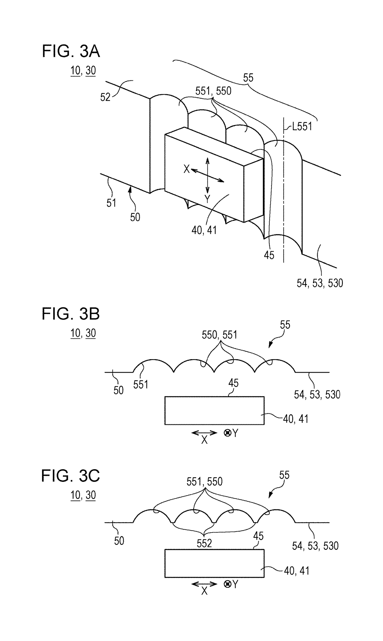
An illuminating device includes a light emitting element constituted of a light emitting diode, and a light guide plate including a light receiving section provided on a side face and opposed to the light emitting element. The light guide plate emits illuminating light from a first surface. The light receiving section includes a plurality of cylindrical lens surfaces each formed of a concave curved surface oriented such that an axial direction of the curved surface is parallel to a thickness direction of the light guide plate, the cylindrical lens surfaces being aligned in a direction orthogonal to the axial direction. The cylindrical lens surface is formed of an arcuate surface having a curvature radius of 0.5 mm or less, and more preferably 0.2 mm or less.

Description

BACKGROUND[0001]1. Technical Field[0002]The present invention relates to an illuminating device, a display device, and a portable electronic device that include a light guide plate and a light emitting element.[0003]2. Related Art[0004]In display devices including a reflective display panel, an illuminating device called frontlight is employed, because transmitted light is unable to be utilized. In such an illuminating device, light is made incident on a side face of a light guide plate, and illuminating light is emitted through one of the surfaces of the light guide plate in the thickness direction. When the display device is employed in a portable electronic device, a light emitting element such as a light emitting diode is employed as light source. In this case, the display panel has to be evenly illuminated with a fewer number of light emitting elements, from the viewpoint of energy saving.[0005]However, in the case where a light receiving section 55 of a light guide plate 50 is...

Claims


Application Information

Patent Timeline
Patent Type & Authority Patents(United States)
IPC IPC(8): F21V8/00
CPCG02B6/0016G02B6/0021G02B6/002F21S8/00F21V2200/20G02B6/003G02B6/0058
Inventor KOBAYASHI, HIDEKAZU
Owner E INK CORPORATION
Learn More