Catheter apparatus for cranial cavity

a catheter and cavity technology, applied in the field of cranial cavities, can solve the problems of increased intracranial pressure, cumbersome manipulation, and increased risk of infection, and achieve the effect of convenient rear end tunneling and accurate positioning

Inactive Publication Date: 2019-02-19
LEE JE BUM
View PDF5 Cites 3 Cited by
  • Summary
  • Abstract
  • Description
  • Claims
  • Application Information

AI Technical Summary

Benefits of technology

[0019]Therefore, the present invention has been made in view of the above problems, and it is an object of the present invention to provide a catheter apparatus for cranial cavities which exhibits the advantage of a conventional catheter structure in that a medicine and a bodily fluid are transferred along different paths, uniformizes the outer diameter of a catheter so as to easily use stereotactic equipment to accurately locate the end of the catheter in the cerebral ventricle, and facilitates tunneling of the rear end of the catheter in a bypass space between the skull and the skin, so as to allow an operation to be simply and easily performed and thus to increase safety in operation.

Problems solved by technology

However, since such a conventional catheter apparatus has one drain pipe serving as a single fluid path, when it is necessary to inject a thrombolytic agent, an antibiotic or a saline solution, a considerable amount of a bodily fluid, such as a hematoma or a cerebrospinal fluid, filling the inside of the catheter should be introduced again into the brain and the saline solution of an amount corresponding to the inner volume of the catheter should be additionally injected, and thus, the conventional catheter apparatus causes increased intracranial pressure, the risk of infection due to repeated injection and cumbersomeness in manipulation.
Therefore, it is difficult to use stereotactic equipment and to perform tunneling of the rear end of the catheter 12 between the skull 6 and the skin 2, thus causing difficulty and complexity in operation.

Method used


Image

  • Catheter apparatus for cranial cavity
  • Catheter apparatus for cranial cavity
  • Catheter apparatus for cranial cavity

Examples


Embodiment Construction

[0030]Hereinafter, preferred embodiments of the present invention will be described with reference to the annexed drawings.

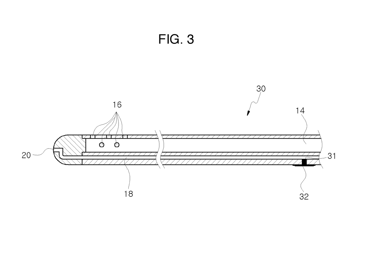
[0031]FIG. 3 is a cross-sectional view illustrating a catheter for cranial cavities in accordance with one embodiment of the present invention, FIG. 4 is a cross-sectional view illustrating the catheter for cranial cavities in accordance with the embodiment of the present invention which is provided with a binding member, FIG. 5 is a view illustrating a connection state among a plastic pipe, an extension tube and a syringe, and FIGS. 6A, 6B and 6C are perspective views illustrating a connection state of the binding member of FIG. 4.

[0032]With reference to FIGS. 3 to 6C, a catheter apparatus for cranial cavities in accordance with one embodiment of the present invention exhibits the advantage of a conventional catheter structure in that a medicine and a bodily fluid are transferred along different paths, uniformizes the outer diameter of a catheter so as to easil...


PUM


Abstract

Disclosed herein is a catheter apparatus for cranial cavities which exhibits the advantage of a conventional catheter structure in that a medicine and a bodily fluid are transferred along different paths, uniformizes the outer diameter of a catheter to easily use stereotactic equipment, and facilitates tunneling of the rear end of the catheter in a bypass space between the skull and the skin, so as to allow an operation to be simply and easily performed and thus to increase safety in operation. The catheter apparatus is advantageous in that no protrusion is formed on the outer surface of the catheter and thus the end of the catheter may be easily and accurately located in a cerebral ventricle using the stereotactic equipment, the catheter may be easily bent through the bypass space, and the rear end of the catheter may be easily exposed to the outside through a perforated part.

Description

BACKGROUND OF THE INVENTION[0001]Field of the Invention[0002]The present invention relates to a catheter apparatus for cranial cavities and, more particularly, to a catheter apparatus for cranial cavities which exhibits the advantage of a conventional catheter structure in that a medicine and a bodily fluid are transferred along different paths, uniformizes the outer diameter of a catheter so as to easily use stereotactic equipment to accurately locate the end of the catheter in a cerebral ventricle, and facilitates tunneling of the rear end of the catheter in a bypass space between the skull and the skin, so as to allow an operation to be simply and easily performed and thus to increase safety in operation.[0003]Description of the Related Art[0004]As is well known, hematomas within cerebral ventricles have conventionally been removed together with treatment of diseases through craniotomy which is a neurosurgical operation. However, an operation, in which a catheter is inserted dire...

Claims


Application Information

Patent Timeline
Patent Type & Authority Patents(United States)
IPC IPC(8): A61M3/00A61M25/00A61M25/01A61M25/02
CPCA61M25/02A61M25/0026A61M25/0194A61M2210/0693A61M2025/024A61M2210/0687A61M2025/0197A61M27/006A61M2025/028A61M2025/0042A61M25/007
Inventor LEE, JE BUM
Owner LEE JE BUM
Why Eureka
Try Eureka