Micro splice protector

a protector and micro-splice technology, applied in the field of fusion splice protectors, can solve the problems of compromising splices, requiring the size reduction of included components, limited space for optics and mechanics within these enclosures, etc., and achieves the effect of minimizing any damage to optical fibers and excellent material selection

Active Publication Date: 2019-02-19
II VI DELAWARE INC
View PDF30 Cites 12 Cited by
  • Summary
  • Abstract
  • Description
  • Claims
  • Application Information

AI Technical Summary

Benefits of technology

[0011]Various types of metals, ceramics, metal matrix composites (MMCs) and the like may be used to form the micro splice protector sleeve, where qualities such as being lightweight while exhibiting mechanical strength are important. Besides stainless steel, fused silica has been found to be an excellent material choice for this component. Additionally, it is preferred that the interior surface and end terminations of the sleeve be polished or as smooth as possible to minimize any damage to the optical fibers as the sleeve is positioned over a fiber prior to performing the splice, and then moving the sleeve along the fiber after the splice is made.

Problems solved by technology

There is limited space for optics and mechanics within these enclosures, thus requiring the included components to be reduced in size as much as possible.
Splice protectors serve to shield the fusion splice from bending and experiencing stress, which may introduce signal loss and ultimately cause the splice to be compromised over time.
While these commercially available splice protectors have been useful in the past, they are too large in diameter and length to be readily accommodated into the current CFP package designs (and, accordingly, any future enclosures that may be even smaller).
However, these polymer coatings do not necessarily provide adequate mechanical protection and high reliability, especially for small bend conditions as associated with the CFP enclosures.
These aforementioned solutions, especially commercial splice protectors, have been used in the telecommunications industry for many years, but are not adequate for evolving applications.

Method used


Image

  • Micro splice protector
  • Micro splice protector
  • Micro splice protector

Examples


Embodiment Construction

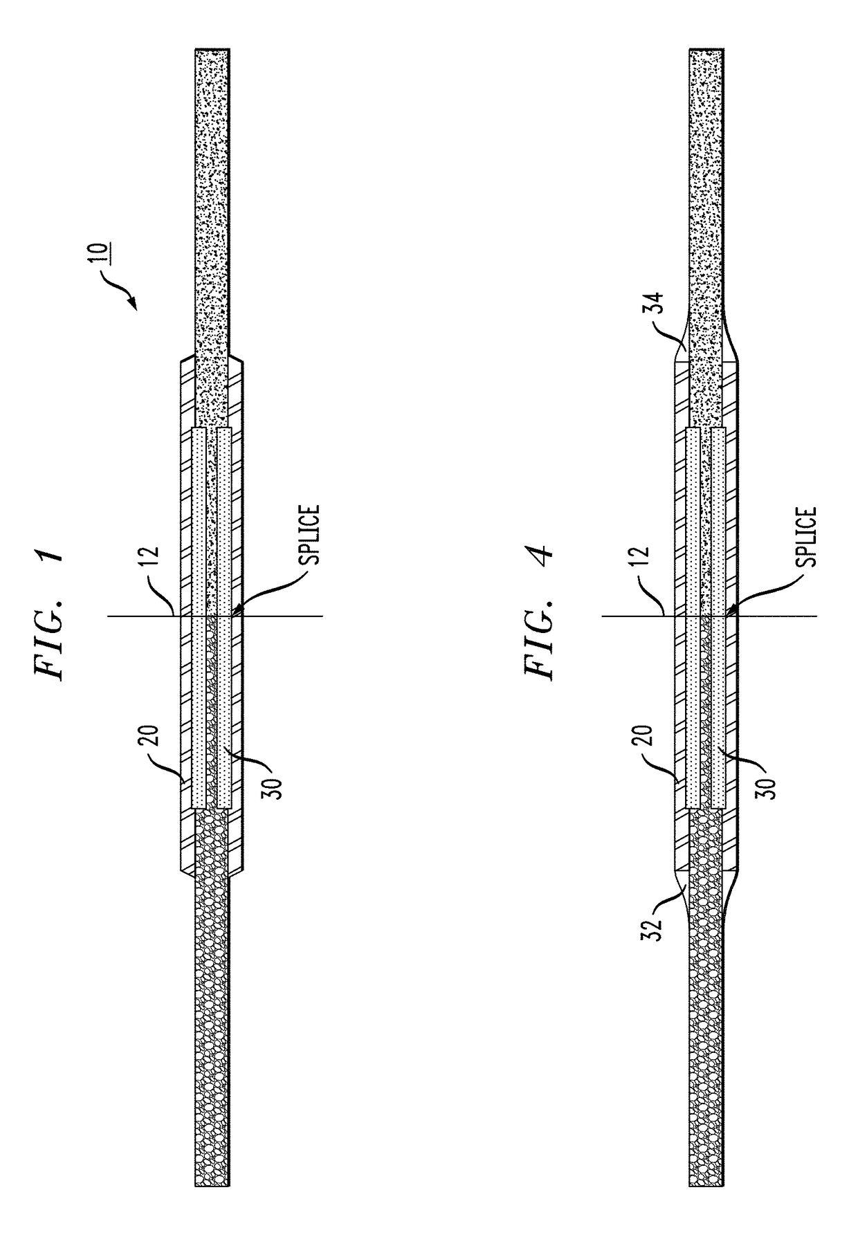
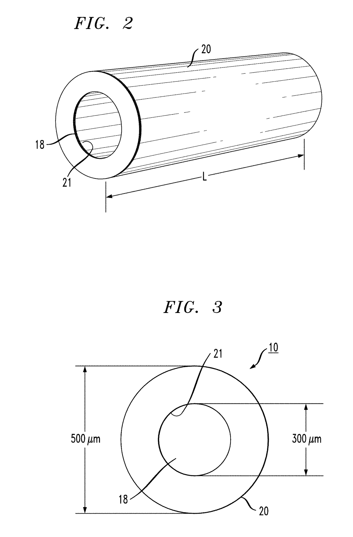
[0034]A new type of splice protector is proposed that is small in size, easy to use, and works well within the current dimensions of CFP-based enclosures. Inasmuch as the inventive splice protector is only a few millimeters larger in cross-section than the fibers themselves, it is contemplated that it will remain useful even as packaging dimensions continue to decrease.

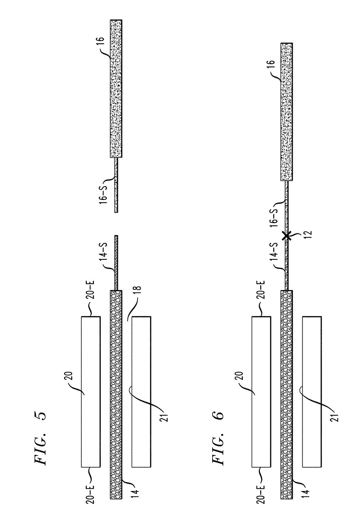
[0035]FIG. 1 is a cut-away side view of an exemplary micro splice protector 10 in place over a fusion splice 12 formed to join a first optical fiber 14 to a second optical fiber 16. As is well-known in the art, a fusion splice is created between endfaces of a pair of optical fibers that have been stripped to remove outer jacket and coating layers, leaving only the silicon-based core and cladding regions of the fibers. An electric arc, or other type of high energy pulse, is applied to the abutting endfaces so as to essentially melt the silicon material in a manner that joins the two fibers together. While a fusion spli...


PUM


Abstract

A micro splice protector for a fusion connection between a pair of optical fibers takes the form of a cylindrical sleeve of dimensions similar to that of the fusion splice itself, with an epoxy material used to encase the fusion splice within the sleeve. The sleeve is formed to exhibit an inner diameter only slightly greater than the outer diameter of the optical fibers, with the length of the sleeve typically formed to be only slightly longer than the stripped end terminations of the pair of fibers being spliced together. The cylindrical sleeve is formed of a rigid, but lightweight, material (e.g., stainless steel, fused silica) and an epoxy material is injected into the configuration to fill any gaps between the fusion connection and the inner surface of the sleeve. The result is relatively stiff fusion splice protector that is extremely small in size and well-suited for use in optical component packages where space is at a minimum.

Description

CROSS-REFERENCE TO RELATED APPLICATIONS[0001]This application claims the benefit of U.S. Provisional Application Ser. No. 62 / 217,689, filed Sep. 11, 2015 and herein incorporated by reference.TECHNICAL FIELD[0002]The present invention relates to the utilization of fusion splices in optical fiber connections and, more particularly, to a fusion splice protector in the form of a cylindrical sleeve of rigid material with epoxy used to affix the splice in place within the sleeve, where the diameter of the sleeve is only slight larger than the fibers themselves.BACKGROUND OF THE INVENTION[0003]In the continuing development of optical communication systems, components such as optical amplifiers need to fit into smaller and smaller enclosures (e.g., common form-factor pluggable packages such as CFP, CFP2, CFP4 transceivers and the like). There is limited space for optics and mechanics within these enclosures, thus requiring the included components to be reduced in size as much as possible.[0...

Claims


Application Information

Patent Timeline
Patent Type & Authority Patents(United States)
IPC IPC(8): G02B6/255G02B6/245
CPCG02B6/2558G02B6/2551G02B6/245
Inventor FILIPOWICZ, MARKTRAN, TOAN
Owner II VI DELAWARE INC
Why Eureka
Try Eureka