
System and method of determining a limit fault in an HVAC unit

a technology of limit fault and hvac unit, which is applied in the field of system and method of determining limit fault in hvac unit, can solve the problems of system controller (e.g. thermostat) going blank, operating above the threshold temperature could pose a hazard to both the hvac system and the space in which the hvac system is located,

Active Publication Date: 2019-02-26
CARRIER CORP
View PDF18 Cites 3 Cited by
  • Summary
  • Abstract
  • Description
  • Claims
  • Application Information

AI Technical Summary

Benefits of technology

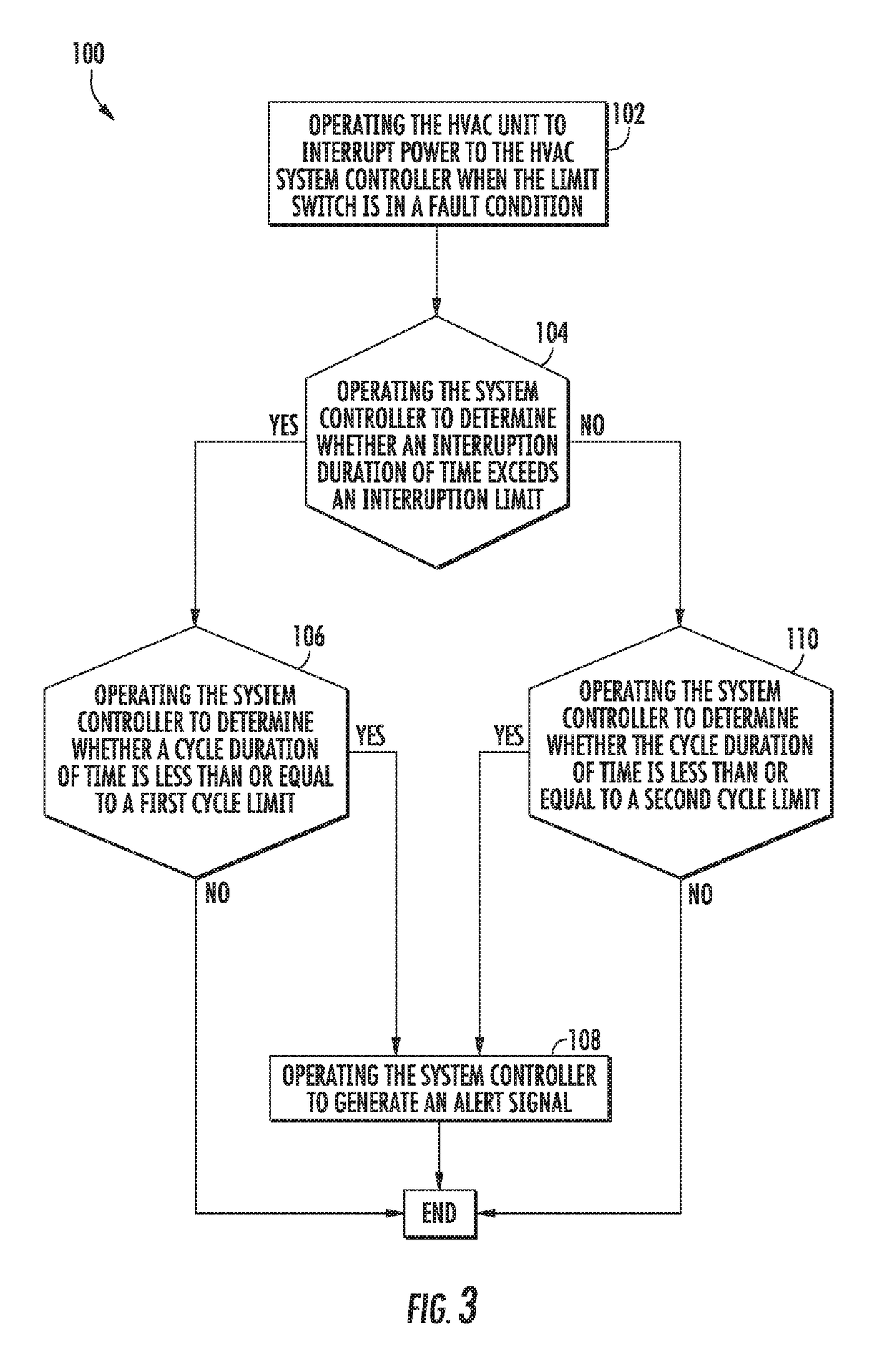
The patent describes an HVAC system that includes a temperature-sensitive limit switch and a system controller. The system controller is responsible for interrupting power when the temperature-sensitive limit switch detects a high temperature. The system controller uses a program to determine if the interruption duration of time (the time between interruptions of power) exceeds a predetermined limit. If so, the system controller generates an alert signal, which can be visual, auditory, or electronic, to alert the user of the malfunction. The program also determines if the cycle duration of time (the amount of time between consecutive interruptions of power) is within a specific range. If the cycle duration of time is too short, the system controller alerts the user that the blower of the HVAC unit may be malfunctioning. The technical effect of this patent is to provide an improved method for detecting and addressing malfunctions in an HVAC system, which can prevent damage and improve efficiency.

Problems solved by technology

Operation above the threshold temperature could pose a hazard to both the HVAC system and the space that the HVAC system is located within.
Also, the system controller (e.g. thermostat), may go blank due to the loss of power.

Method used


Image

  • System and method of determining a limit fault in an HVAC unit
  • System and method of determining a limit fault in an HVAC unit
  • System and method of determining a limit fault in an HVAC unit

Examples


Embodiment Construction

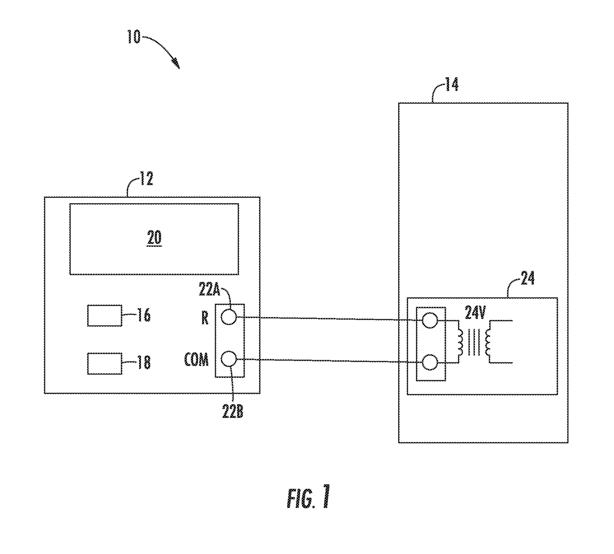
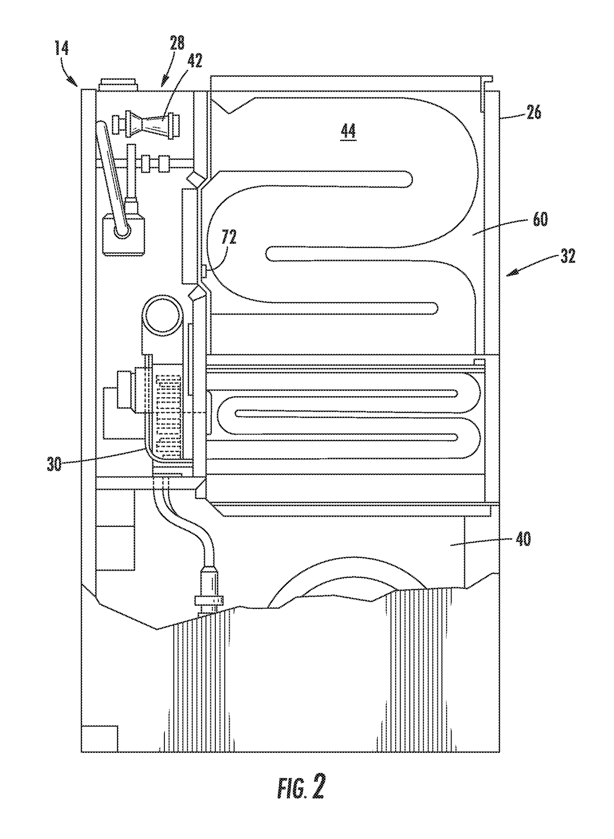
[0005]In one aspect, and HVAC system is provided. The HVAC system includes an HVAC unit configured to interrupt power when a temperature sensed by a temperature sensitive limit switch exceeds a predetermined temperature, and a system controller in electrical communication with the HVAC unit, the system controller is configured to determine a temperature limit switch fault based upon an interruption duration of time and a cycle duration of time, wherein the cycle duration of time is indicative of an amount of time between consecutive interruptions of power. In one embodiment, the system controller is in wireless electrical communication with the HVAC unit. In an embodiment, the system controller includes a thermostat.

[0006]In an embodiment, the system controller is further configured to generate an alert signal if it is determined that the interruption duration of time of consecutive interruptions of power does not exceed the interruption limit and the cycle duration of time is less ...


PUM


Abstract

A system and method of determining a limit fault in an HVAC unit the HVAC unit in electrical communication with an HVAC system controller, by operating the system controller to determine whether an interruption duration of time exceeds an interruption limit, operating the system controller to determine whether a cycle duration of time is less than or equal to a first cycle limit, wherein the cycle duration of time is indicative of an amount of time between consecutive interruptions of power, and generating an alert signal if the interruption duration of time of the consecutive interruptions of power exceeds the interruption limit and the cycle duration of time is less than or equal to the first cycle limit.

Description

CROSS-REFERENCE TO RELATED APPLICATIONS[0001]The present application is a nonprovisional patent application, which claims priority to U.S. Provisional Patent Application Ser. No. 62 / 214,006, filed Sep. 3, 2015, and having the title “SYSTEM AND METHOD FOR DETERMINING A LIMIT FAULT IN AN HVAC UNIT,” which is herein incorporated in its entirety.TECHNICAL FIELD OF THE DISCLOSED EMBODIMENTS[0002]The presently disclosed embodiments generally relate to appliances for heating and cooling air, and more particularly, to a system and method for determining a limit fault in an HVAC unit.BACKGROUND OF THE DISCLOSED EMBODIMENTS[0003]Typically, modern furnaces and boilers include a temperature sensor; often called a limit switch, to detect when components of the HVAC system are operating above a threshold temperature. Operation above the threshold temperature could pose a hazard to both the HVAC system and the space that the HVAC system is located within. Generally, when a limit switch opens durin...

Claims


Application Information

Patent Timeline
Patent Type & Authority Patents(United States)
IPC IPC(8): F24F11/00F24F11/62F24F11/30F24F11/32F24F11/64F24F11/61F24F110/00
CPCF24F11/62F24F11/30F24F2110/00F24F11/61F24F11/64F24F11/32F24F11/52F24F11/526F24F11/38
Inventor DEMPSEY, DANIEL J.
Owner CARRIER CORP
Learn More