Camera module

a technology of camera module and camera body, which is applied in the field of camera module, can solve the problems of disadvantageous need for a larger size of the conventional camera, complex structure, etc., and achieve the effect of large changes, clean image, and efficient present invention

Active Publication Date: 2019-02-26
LG INNOTEK CO LTD
View PDF11 Cites 2 Cited by
  • Summary
  • Abstract
  • Description
  • Claims
  • Application Information

AI Technical Summary

Benefits of technology

[0030]Since the present invention heats a lens by wirelessly supplying power to a heating element through simple configurations such as a transmission coil and the heating element, large changes are unnecessary in the volume and the structure of a camera module.
[0031]In addition, since the heating element of the present invention does not restrict incident light, an image of a subject is not distorted and a clean image can be obtained, and thus the present invention is efficient.
[0032]In addition, the present invention prevents signal interference with other electronic components or electrical components when power is wirelessly supplied to a heating element, and thus, camera malfunction can be prevented.

Problems solved by technology

However, in order to apply a power to a heater, an electric wire is connected and in order to make the heater including the electric wire water-proof, a complex structure may be required to disadvantageously need a structure larger in size than that of the conventional camera.

Method used


Image

  • Camera module
  • Camera module
  • Camera module

Examples


first exemplary embodiment

[0044]Hereinafter, a camera module according to a first exemplary embodiment of the present invention will be described with reference to accompanying drawings.

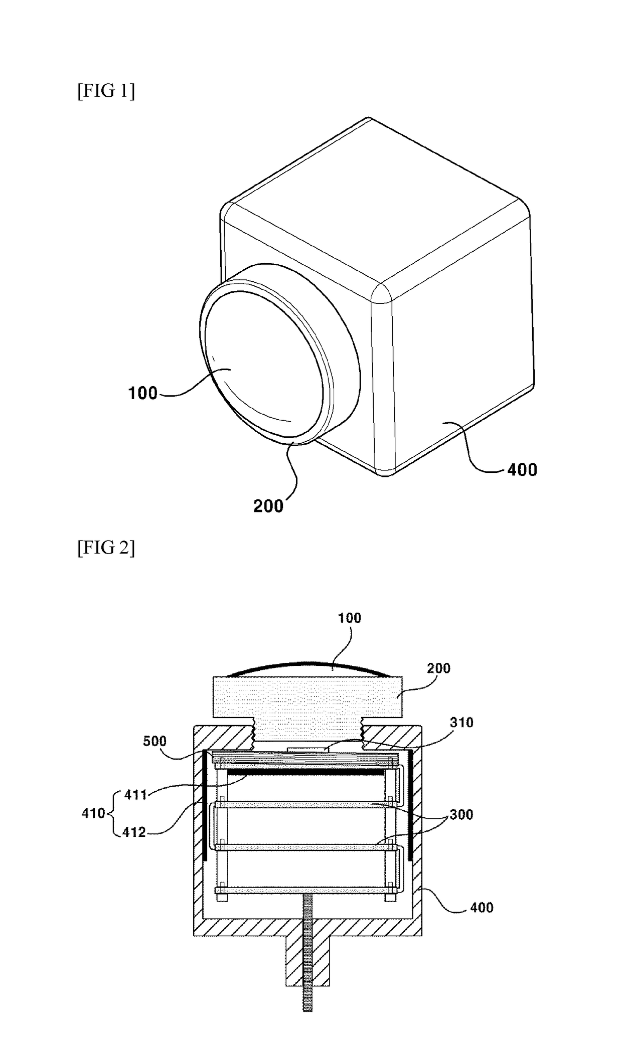
[0045]FIG. 1 is perspective view illustrating a camera module according to an exemplary embodiment of the present invention, and FIG. 2 is a schematic cross-sectional view illustrating a camera module according to an exemplary embodiment of the present invention.

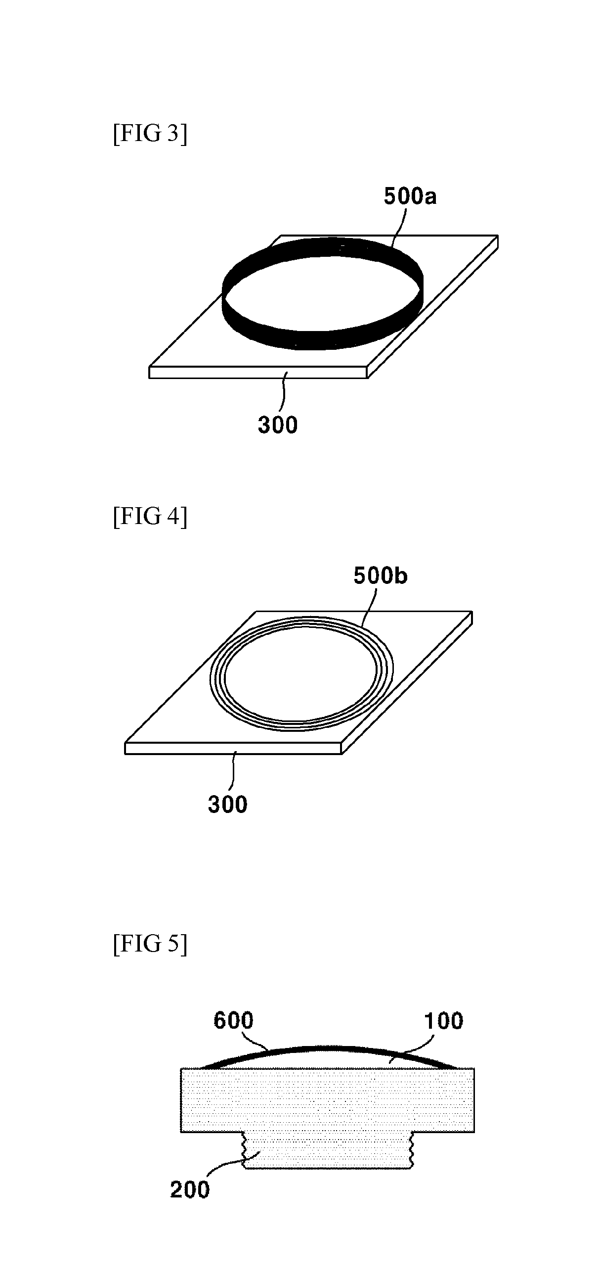
[0046]Referring to FIGS. 1 and 2, the camera module according to an exemplary embodiment of the present invention may include a lens unit (100), a lens barrel (200), a substrate unit (300), a housing (400), a transmission coil (500) and a heating element (600).

[0047]The lens unit (100) may be such that at least one lens (no reference numeral) is arranged along an optical axis and may be accommodated inside the lens barrel (200). The lens barrel (200) may fix the lens unit (100) by accommodating the lens unit (100) inside the lens barrel, lest optical axes formed by th...

second exemplary embodiment

[0065]Hereinafter, a camera module according to a second exemplary embodiment of the present invention will be described with reference to accompanying drawings. In describing the camera module according to the second exemplary embodiment of the present invention, same reference numerals as those in the first exemplary embodiment will be used for same elements and any redundant explanation will be omitted.

[0066]The camera module according to the second exemplary embodiment of the present invention is different from the first exemplary embodiment in that the lens barrel (200) in the camera module according to the second exemplary embodiment of the present invention is formed with a metal. When the lens barrel (200) in the camera module according to the second exemplary embodiment of the present invention is formed with a metal, an electromagnetic interaction with the transmission coil (500) can be made possible. For example, an induction current can be generated on the lens barrel (2...

third exemplary embodiment

[0067]Hereinafter, a camera module according to a third exemplary embodiment of the present invention will be described with reference to accompanying drawings. In describing the camera module according to the third exemplary embodiment of the present invention, same reference numerals as those in the first exemplary embodiment will be used for same elements and any redundant explanation will be omitted.

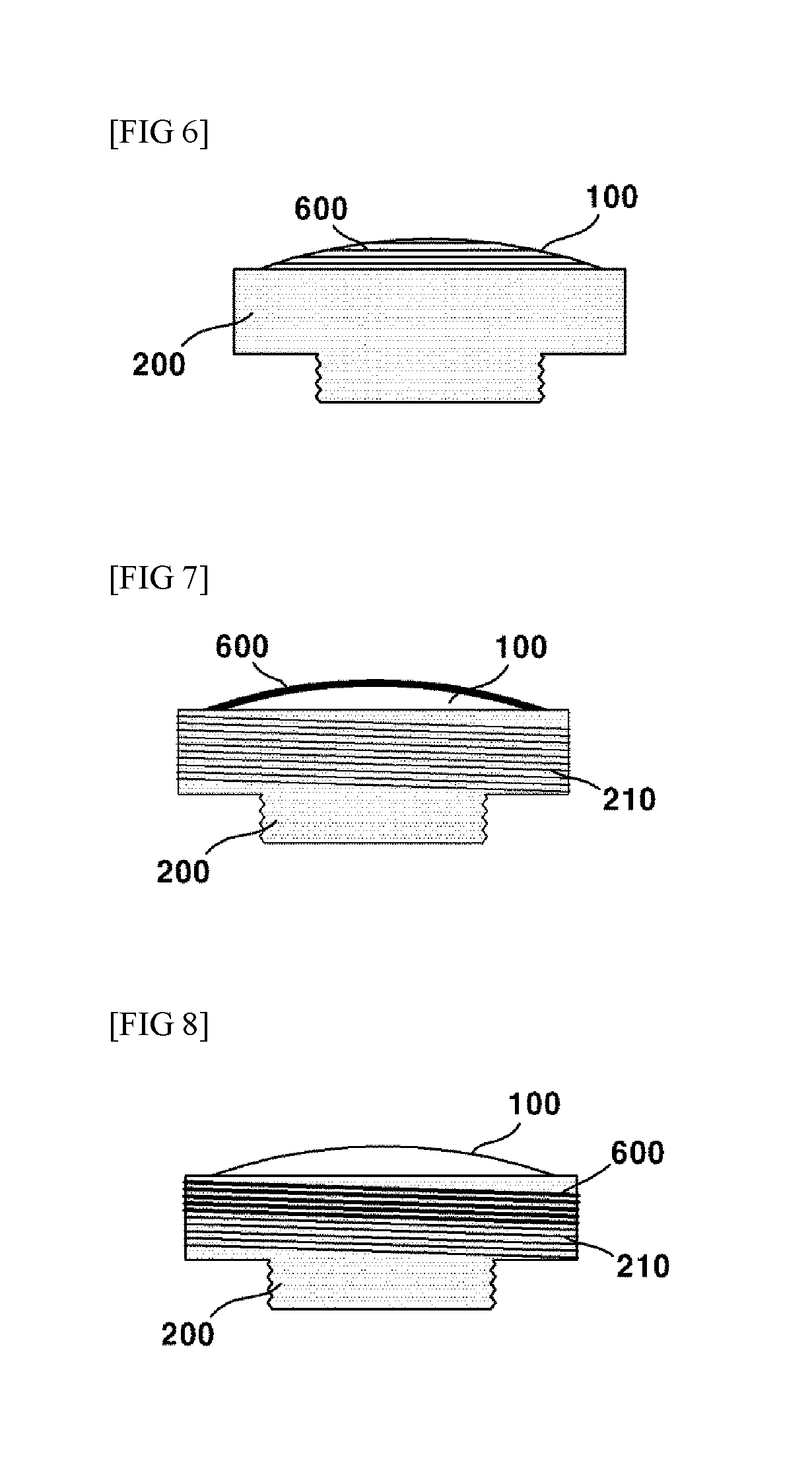
[0068]FIG. 6 is schematic view illustrating a heating element (600) being formed with a pattern on a lens unit of camera module according to an exemplary embodiment of the present invention, the structure of which makes the third exemplary embodiment different from the first and second exemplary embodiments.

[0069]Referring to FIG. 6, the camera module according to the third exemplary embodiment of the present invention may be different from that of the first exemplary in that although the heating element (600) is arranged at an upper surface of the lens unit (100), a predetermined pa...


PUM

PropertyMeasurementUnit
resistanceaaaaaaaaaa

Abstract

The present invention relates to a camera module, and the present invention comprises: a lens unit; a lens barrel for fixing the lens unit; a substrate unit, which has an image sensor mounted thereon, for converting light incident through the lens unit into an electric signal; and a housing accommodating the substrate unit in an inner space thereof and of which one side is coupled to the lens barrel, and the present invention can comprise: a transmission coil accommodated inside the housing so as to form an electric field, and a conductive heating element arranged on an outer surface of the lens unit or on an outer circumferential surface of the lens barrel, and in which an induced current is generated by the electric field formed by the transmission coil. Since the present invention heats a lens by wirelessly supplying power to a heating element through simple configurations such as a transmission coil and the heating element, large changes are unnecessary in the volume and the structure of a camera module. In addition, since the heating element of the present invention does not restrict incident light, an image of a subject is not distorted and a clean image can be obtained, and thus the present invention is efficient. In addition, the present invention prevents signal interference with other electronic components or electrical components when power is wirelessly supplied to a heating element, and thus, camera malfunction can be prevented.

Description

CROSS REFERENCE TO RELATED APPLICATIONS[0001]This application is the National Phase of PCT International Application No. PCT / KR2016 / 007446, filed on Jul. 8, 2016, which claims priority under 35 U.S.C. 119(a) to Patent Application No. 10-2015-0097813, filed in the Republic of Korea on Jul. 9, 2015, all of which are hereby expressly incorporated by reference into the present application.TECHNICAL FIELD[0002]The teachings in accordance with exemplary and non-limiting embodiments of this invention relate generally to a camera module, and more particularly to a camera module for vehicular camera module.BACKGROUND ART[0003]Concomitant with increased demand on convenience and safety for drivers in the automobile industries, new technologies are being variously grafted and particularly, the technologies using cameras are being fused with software technologies to be briskly applied. These cameras are mounted outside of a vehicle to therefore require a clean image even under various climate c...

Claims


Application Information

Patent Timeline
Patent Type & Authority Patents(United States)
IPC IPC(8): G02B7/02H05B6/36G03B17/55H01F38/14H04N5/225B60R11/04B60R11/00
CPCG02B7/028G03B17/55H01F38/14H04N5/2253H04N5/2257H04N5/22521H05B6/36H04N5/2254B60R2011/004B60R11/04G02B27/0006H05B6/105H04N23/52H04N23/55H04N23/54H04N23/57
Inventor PARK, SEUNG RYONGSUNG, JAE HUNSEO, JUNG HOOLEE, SE KYUJEONG, SOO MIN
Owner LG INNOTEK CO LTD
Why Eureka
Try Eureka