Oscillation circuit including an ultraviolet sensor

a technology of ultraviolet sensor and oscillator circuit, which is applied in the field of ultravioletray (uv) sensor, can solve the problems of price competitiveness drop, and achieve the effects of ensuring price competitiveness, improving sensor sensitivity, and large surface area

Active Publication Date: 2019-03-05
KOREA ELECTRONICS TECH INST
View PDF10 Cites 1 Cited by
  • Summary
  • Abstract
  • Description
  • Claims
  • Application Information

AI Technical Summary

Benefits of technology

[0010]An embodiment of the present invention provides an UV sensor technology which is capable of ensuring price competitiveness even when detecting trace of ultraviolet rays.
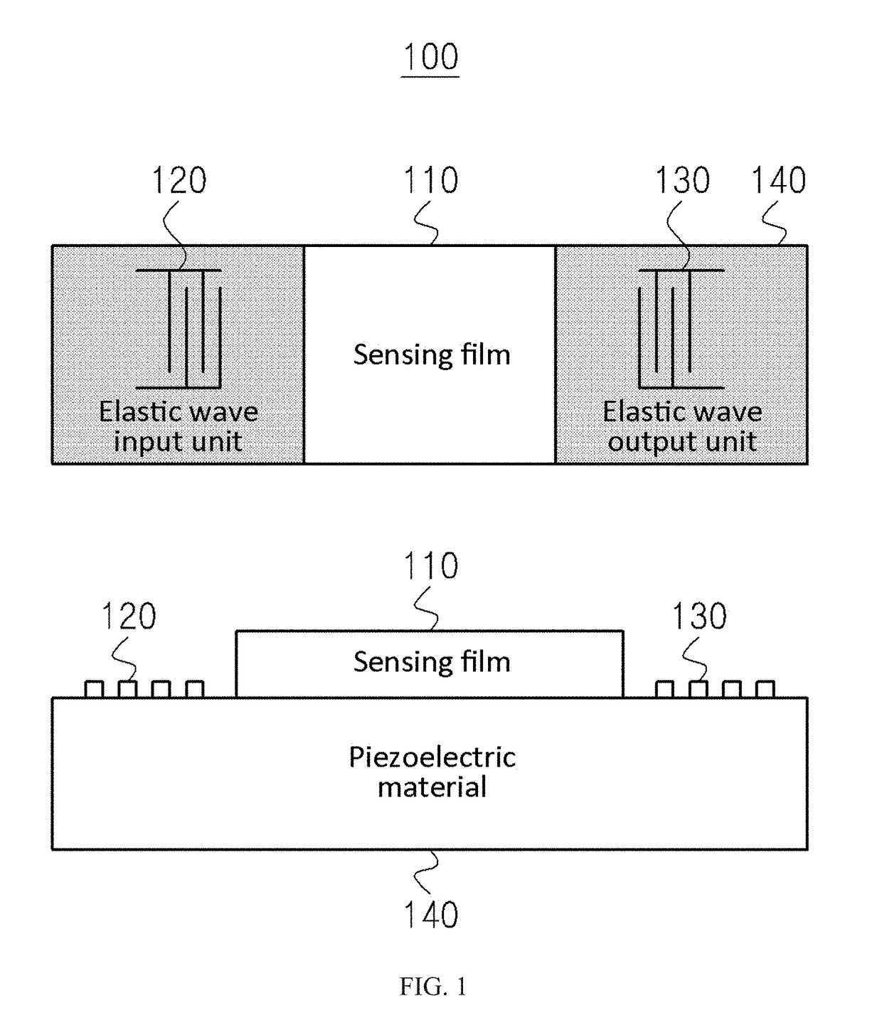
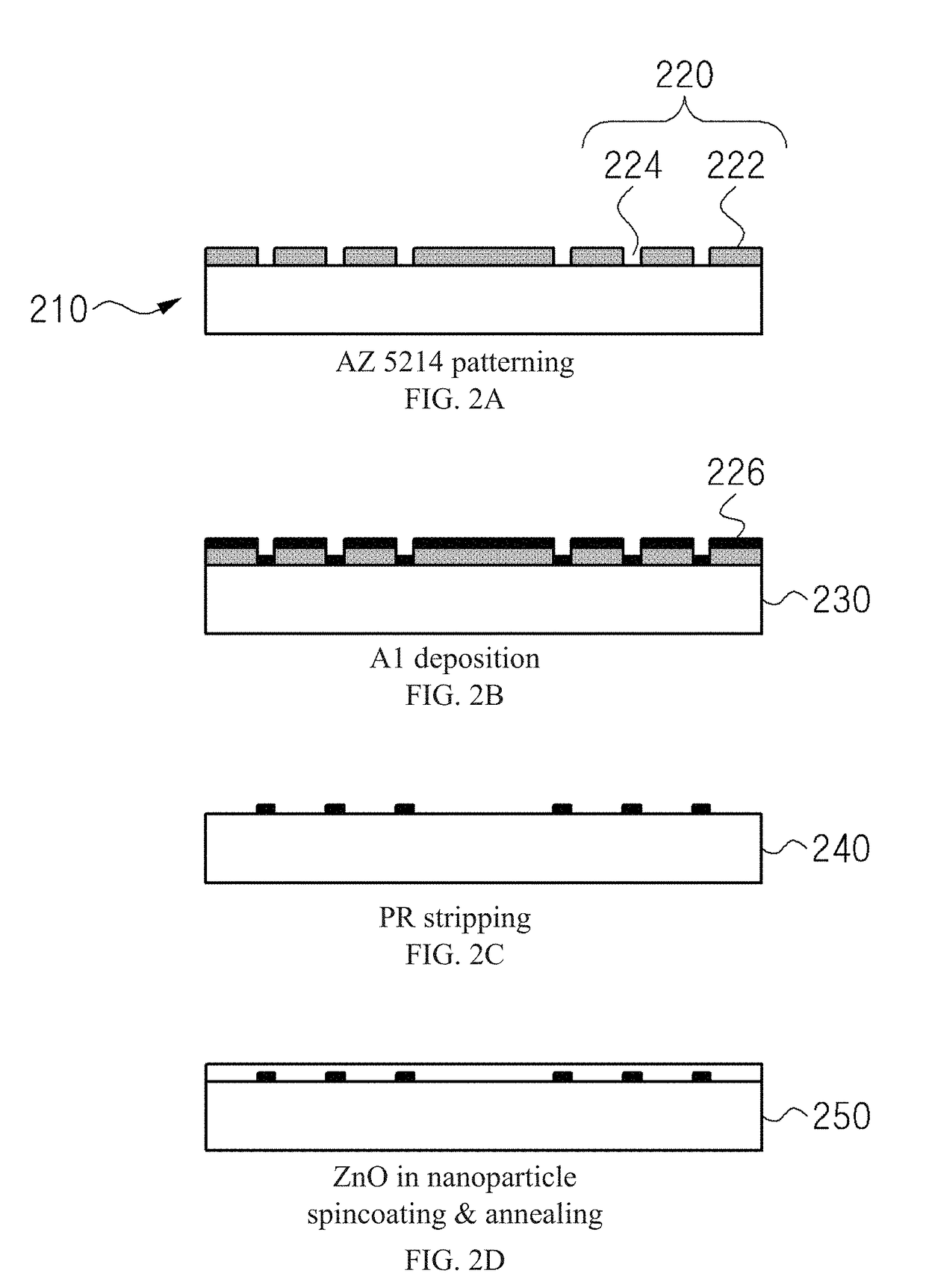
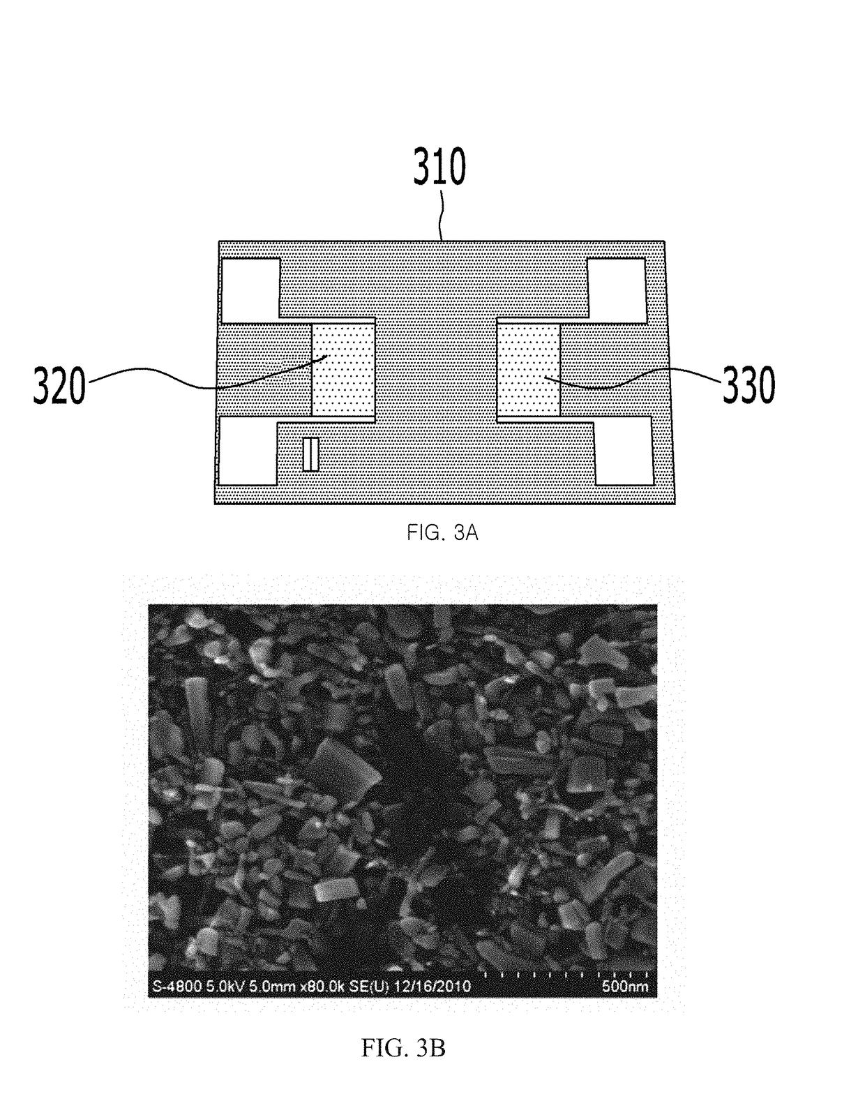
[0013]In an embodiment, the sensing film is formed by spincoating the ZnO nanoparticles on the elastic wave input unit, the elastic wave output unit, and the piezoelectric material. Further, the sensing film may have improved electrical or mechanical properties by annealing the spincoated sensing film.
[0024]A certain embodiments of the present invention has following advantages. However, since a specific embodiment may provide all the following effects or a few of them, the scope of the disclosure is not limited to the following advantages.
[0026]The UV sensor according to an embodiment of the present invention secures price competitiveness since the UV sensor measures a change in frequency of the elastic wave using the ZnO nanoparticles.
[0027]The method of manufacturing the UV sensor according to an embodiment of the present invention improves sensitivity of the sensor by enabling the particles having large surface areas due to their characteristics to react with a larger amount of ultraviolet rays.

Problems solved by technology

There has been a problem that price competitiveness is dropped since trace of detection in an existing method of measuring changes in current of a thin film due to ultraviolet rays requires the advancement of measuring circuits.

Method used


Image

  • Oscillation circuit including an ultraviolet sensor
  • Oscillation circuit including an ultraviolet sensor
  • Oscillation circuit including an ultraviolet sensor

Examples


Embodiment Construction

[0037]It should not be understood that the scope of rights of the disclosed technology is limited by the embodiments described below.

[0038]The terms described in the specification should be understood as follows.

[0039]In the description, the terms “first”, “second” and so on are used to distinguish one element from another element, and the elements are not defined by the above terms.

[0040]If it is mentioned that an element is “coupled” to another element, it should be understood that the element is directly coupled to another element or still another element is interposed therebetween. On the contrary, when it is mentioned that an element is “directly coupled” to another element, it should be understood that still another element is not interposed therebetween. Other expressions explaining a relationship between the elements, i.e., “between” and “directly between”, or “adjacent to” and “directly adjacent to”, and so on should be interpreted in the same manner.

[0041]It should be unde...


PUM


Abstract

An ultraviolet-ray (UV) sensor is disclosed. In one embodiment, the UV sensor includes a piezoelectric material, a sensing film arranged on the piezoelectric material and senses ultraviolet rays, an elastic wave input unit arranged on one end of the sensing film on the piezoelectric material and provides the sensing film with an elastic wave generated based on an electrical signal and an elastic wave output unit arranged on the other end of the sensing film on the piezoelectric material and senses a change in frequency of the electrical signal generated based on the provided elastic wave. The UV sensor improves sensitivity of the sensor by enabling the particles having large surface areas due to their characteristics to react with a larger amount of ultraviolet rays. the UV sensor can secure price competitiveness since the UV sensor measures a change in frequency of the elastic wave using zinc oxide (ZnO) nanoparticles.

Description

CROSS-REFERENCE TO RELATED APPLICATIONS[0001]This application is a continuation application, and claims the benefit under 35 U.S.C. §§ 120 and 365 of PCT Application No. PCT / KR2015 / 007464, filed on Jul. 17, 2015, which is hereby incorporated by reference.BACKGROUNDField[0002]The present disclosure relates to an ultraviolet-ray (UV) sensor, and more specifically, to an UV sensor which is capable of measuring intensity of ultraviolet rays by detecting a change in frequency, and a method of manufacturing the UV sensor.Related Art[0003]UV Tron or a photomultiplier can sense ultraviolet rays. UV Tron is a structure in which the anode and the cathode are connected to a DC power source through series resistance in a state that an anode and a cathode are made to face each other in a container formed of material through which ultraviolet rays pass. Photoelectrons are emitted from the surface of the cathode by the photoelectric effect when ultraviolet rays are irradiated onto the cathode from...

Claims


Application Information

Patent Timeline
Patent Type & Authority Patents(United States)
IPC IPC(8): G01J1/42H01L31/09H03H9/02G01J1/44
CPCG01J1/429G01J1/42H03H9/02976H01L31/09G01J2001/4446G01J1/46
Inventor KIM, KUNNYUNKWAK, YEON HWAOH, HAE KWAN
Owner KOREA ELECTRONICS TECH INST
Why Eureka
Try Eureka