Optical fiber

a technology of optical fiber and fiber core, applied in the field of optical fiber, can solve the problems of increasing the fusion-splicing loss, and reducing the mfd of optical fiber, and achieving the effect of small bending loss

Active Publication Date: 2019-03-05
SUMITOMO ELECTRIC IND LTD
View PDF1 Cites 1 Cited by
  • Summary
  • Abstract
  • Description
  • Claims
  • Application Information

AI Technical Summary

Benefits of technology

[0007]The present invention provides an optical fiber having a MAC value that is equal to the MAC value of a general SMF that conforms to ITU-T Recommendation G.652, with a small bending loss.
[0012]The optical fiber according to the above aspect of the present invention has a MAC value that is equal to the MAC value of a general SMF that conforms to ITU-T Recommendation G.652, with small bending loss.

Problems solved by technology

However, an optical fiber having a reduced MFD exhibits increased MFD mismatching with respect to the general SMF.
Such mismatching increases the fusion-splicing loss.
Moreover, an optical fiber having increased λc can no longer be guaranteed in terms of the single-mode behavior of signal light.

Method used


Image

  • Optical fiber
  • Optical fiber
  • Optical fiber

Examples


first embodiment

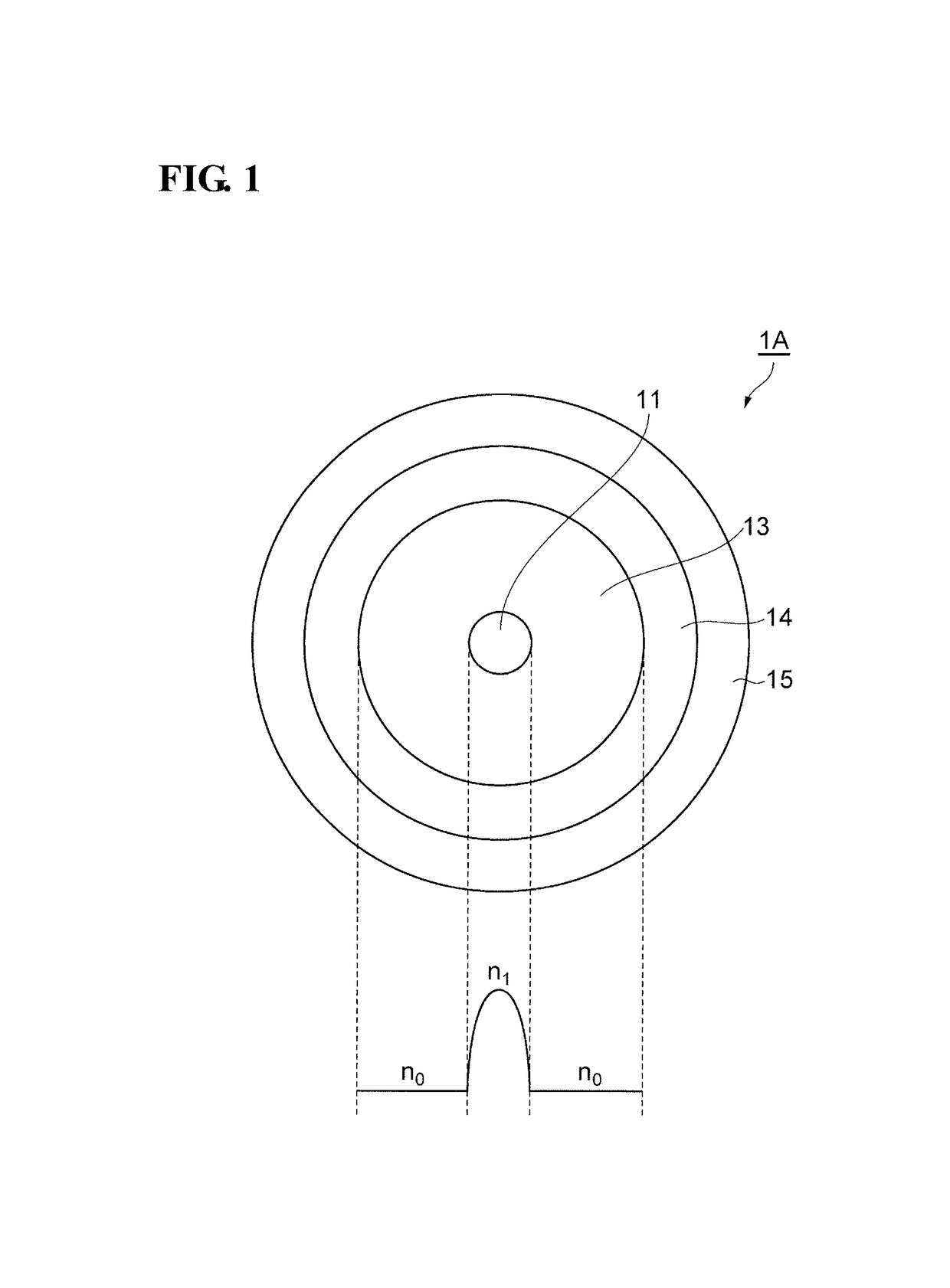
[0031]FIG. 1 is a conceptual diagram illustrating a cross section and the radial refractive-index profile of an optical fiber 1A according to a first embodiment. The optical fiber 1A includes a core 11 and cladding 13 provided around the core 11. The core 11 has a maximum refractive index n1. The cladding 13 has a refractive index n0 that is lower than n1. The core 11 is made of silica glass containing GeO2, and the cladding 13 is made of pure silica glass, for example.

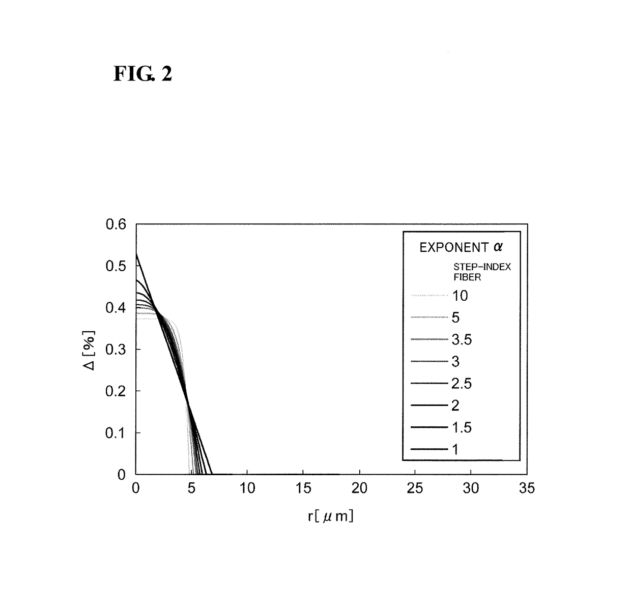
[0032]A radial refractive-index profile n(r) of the optical fiber 1A is approximated with an exponent α as Expression (1):

[0033]n⁡(r)={n1⁡[1-2⁢Δ1⁡(ra)α]12(0≤r≤a)n0(r≥a)(1)

where r denotes the radial distance from the center of the core 11, a denotes the radius of the core 11, at which the refractive index n(r) becomes equal to the refractive index n0 of the cladding 13, and Δ1 denotes the relative refractive-index difference between the center of the core 11 where the refractive index is largest and the cladding 13. Th...

second embodiment

[0041]FIG. 6 is a conceptual diagram illustrating a cross section and the radial refractive-index profile of an optical fiber 1B according to a second embodiment. The optical fiber 1B includes a core 11, a depressed portion 12 provided around the core 11, and cladding 13 provided around the depressed portion 12. The core 11 has a maximum refractive index n1. The cladding 13 has a refractive index n0 that is lower than n1. The depressed portion 12 has a refractive index n2 that is lower than both n1 and n0. The core 11 is made of silica glass containing GeO2, the depressed portion 12 is made of silica glass containing F, and the cladding 13 is made of pure silica glass, for example.

[0042]A radial refractive-index profile n(r) of the optical fiber 1B is approximated with an exponent α as Expression (3):

[0043]n⁡(r)={n1⁡[1-2⁢Δ1⁡(ra)α]12(0≤r≤a)n2(a≤r≤b)n0(r≥b)(3)

where r denotes the radial distance from the center of the core 11, a denotes the radius of the core 11, at which the refractiv...

examples

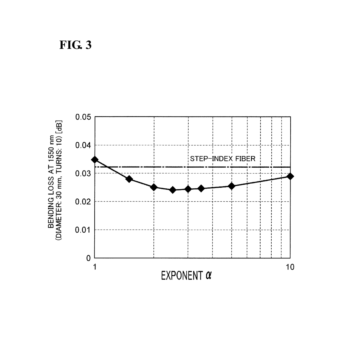
[0055]FIG. 15 is a table summarizing relevant factors of Fibers 1 to 8 according to examples. FIG. 16 is a table summarizing relevant factors of Fibers 9 to 15 according to other examples. The factors summarized in these tables are as follows, in order from the top: the exponent α, the relative refractive-index difference Δ1 at the center of the core 11, the relative refractive-index difference Δ2 of the depressed portion 12, a core diameter 2a, an outside diameter 2b of the depressed portion 12, the ratio (b / a), the zero-dispersion wavelength, the MFD at a wavelength of 1310 nm, an effective cross-sectional area Aeff at a wavelength of 1310 nm, the MFD at a wavelength of 1550 nm, an effective cross-sectional area Aeff at a wavelength of 1550 nm, the fiber cutoff wavelength λc, the cable cutoff wavelength λcc, the difference (λc−λcc), the MAC value, and the bending loss at a wavelength of 1550 nm for the optical fiber 1B wound by ten turns with a bend diameter of 30 mm.

[0056]Fibers ...


PUM


Abstract

An optical fiber includes a core having a maximum refractive index n.sub.1, and cladding provided around the core and having a refractive index n.sub.0 that is lower than the maximum refractive index n.sub.1. A radial refractive-index profile of the core is expressed with an exponent .alpha. that is 1.5 to 10. A relative refractive-index difference .DELTA..sub.1 at a center of the core that is expressed as .DELTA..sub.1=100.times.(n.sub.1.sup.2-n.sub.0.sup.2) / (2n.sub.1.sup.2) is 0.3% to 0.5%. A diameter 2a of the core is 9 .mu.m to 14 .mu.m. A zero-dispersion wavelength is 1300 nm to 1324 nm. A cable cutoff wavelength .lamda.cc is 1260 nm or shorter. A bending loss at a wavelength of 1550 nm in a case where the optical fiber is wound by ten turns with a bend diameter of 30 mm is 0.25 dB or smaller.

Description

BACKGROUND OF THE INVENTION[0001]Field of the Invention[0002]The present invention relates to an optical fiber.[0003]Description of the Related Art[0004]A single-mode optical fiber (SMF) defined by Telecommunication Standardization Sector of International Telecommunication Union (ITU-T) in Recommendation G.652, an international standard, is used worldwide as the most general optical fiber for optical communication systems. According to Recommendation G.652, the mode field diameter (MFD) of the SMF at a wavelength of 1310 nm shall be 8.6 μm to 9.2 μm in nominal value (with a tolerance of ±0.4 μm). If the MFD falls within this range, the MFD mismatching between SMFs to be fusion-spliced with each other at the respective end facets thereof can be made small, whereby the fusion-splicing loss can be made small. Recommendation G.652 also defines that the SMF shall have a cable cutoff wavelength λcc of 1260 nm or shorter. If λcc falls within this range, the single-mode behavior of signal l...

Claims


Application Information

Patent Timeline
Patent Type & Authority Patents(United States)
IPC IPC(8): G02B6/02G02B6/036G02B6/028
CPCG02B6/02014G02B6/03627G02B6/0281G02B6/028
Inventor YAMAMOTO, YOSHINORI
Owner SUMITOMO ELECTRIC IND LTD
Why Eureka
Try Eureka