
Dispersion shifted optical fiber

a technology of optical fiber and dispersion slope, applied in the direction of optical fiber with multi-layer core/cladding, optical waveguide light guide, instruments, etc., can solve the problems of large dispersion slope, difficult to achieve both an enlargement in the effective core area and a reduction in the dispersion slope, and small bending loss, preventing transmission loss for worsening, and reducing the effect of deterioration of transmission characteristics

Inactive Publication Date: 2004-08-31
THE FUJIKURA CABLE WORKS LTD
View PDF55 Cites 2 Cited by
  • Summary
  • Abstract
  • Description
  • Claims
  • Application Information

AI Technical Summary

Benefits of technology

Note that it is possible to obtain a chromatic dispersion value in the used wavelength band within the range of -6 to +6 ps / km / nm. However, if the chromatic dispersion value is zero, then, because it is easy for four-wave mixing, which is one of the non-linear effects, to be generated, it is preferable if the used wavelength band is set so that it does not include a range where the chromatic dispersion value may become zero.
In the present embodiment, the chromatic dispersion absolute value in the wavelength band that is set in a range between 0.5 to 8 ps / km / nm. Namely, the chromatic dispersion value of the dispersion shifted optical fiber of the present embodiment can be set as a positive value and can also be set as a negative value. If the value is less than 0.5 ps / km / nm, the chromatic dispersion value becomes close to zero and it is easy for four-wave mixing, which is one of the non-linear effects, to occur. If it is in excess of 8 ps / km / nm, the deterioration in the transmission characteristics may become somewhat too large.

Problems solved by technology

A large dispersion slope is therefore undesirable.
However, in conventionally proposed dispersion shifted optical fibers under the preconditions that essentially the transmission path be single mode and that bending loss be held to 100 dB / m or less, it has been difficult to achieve both an enlargement in the effective core area and a reduction in the dispersion slope.

Method used

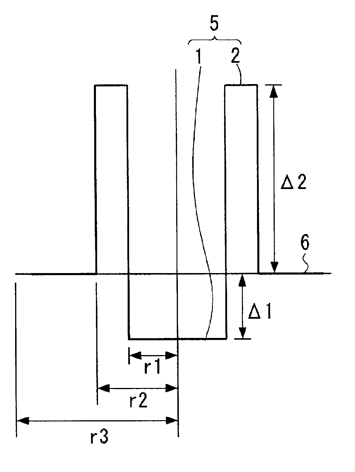
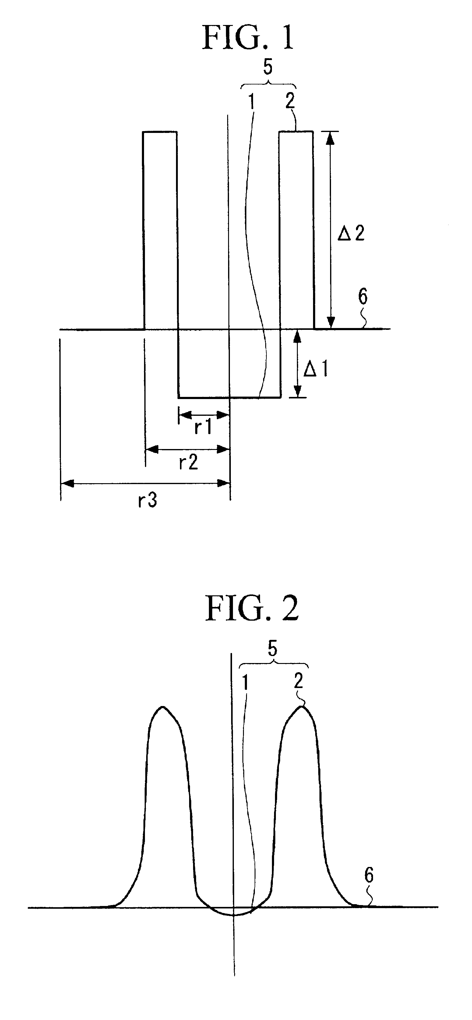
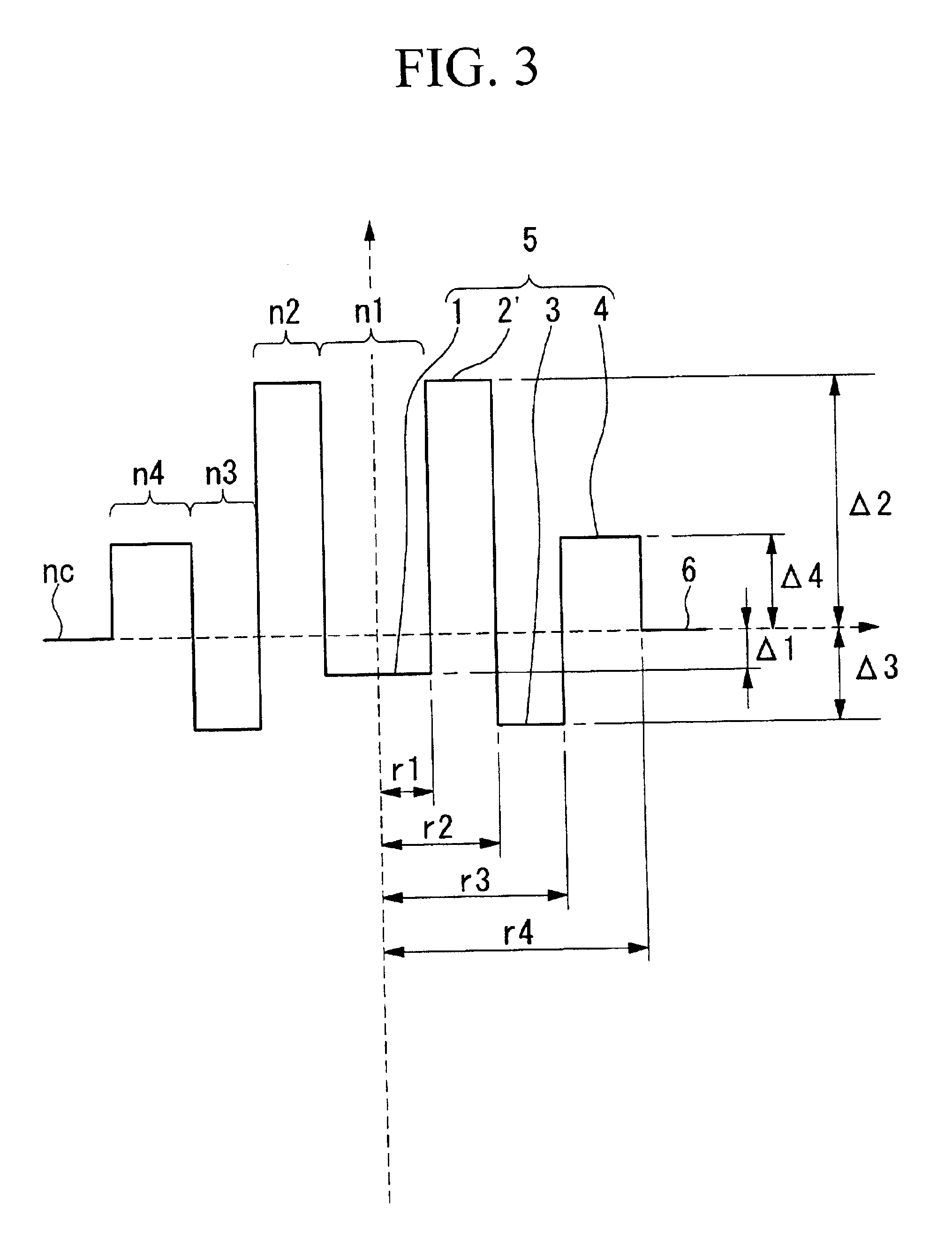

Image

  • Dispersion shifted optical fiber
  • Dispersion shifted optical fiber
  • Dispersion shifted optical fiber

Examples


first embodiment

A. Examples Pertaining to the First Embodiment

Examples 1-1 to 1-3

The dispersion shifted optical fibers of Examples 1-1 to 1-3 were manufactured in accordance with VAD method under the conditions shown in Table 1.

Note that in Examples 1-1 to 1-3, the central core portions are formed from fluorine doped quartz glass, the peripheral core portions are formed from germanium doped quartz glass, and the cladding is formed from pure quartz glass.

In addition, the outer diameters of the dispersion shifted optical fibers (i.e. the outer diameter of the cladding) are set at 125 .mu.m. The characteristic values in the 1550 nm wavelength of the dispersion shifted optical fibers are shown together in Table 1.

As is shown in Table 1, each of the effective core area, the chromatic dispersion value, the dispersion slope, the bending loss, and the cutoff wavelength (.lambda.c) were able to provide the characteristics of the dispersion shifted optical fiber of the present invention. Namely, a dispersion...

second embodiment

B. Examples Pertaining to the Second Embodiment

Examples 2-1 to 2-3

The dispersion shifted optical fibers of Examples 2-1 to 2-3 were manufactured in accordance with VAD method under the conditions shown in Table 2.

Note that in Examples 2-1 to 2-3, the peripheral core portions are formed from germanium doped quartz glass, and the cladding is formed from pure quartz glass. In Example 2-1, the central core portion is formed from fluorine doped quartz glass, in Example 2-2, the central core portion is formed from pure quartz glass, and in Example 2-3, the central core portion is formed from germanium doped quartz glass. In addition, the outer diameters of the dispersion shifted optical fibers (i.e. the outer diameter of the cladding) are set at 125 .mu.m. The characteristic values in the 1550 nm wavelength of the dispersion shifted optical fibers are shown together in Table 2.

As is shown in Table 2, each of the effective core area, the chromatic dispersion value, the dispersion slope, th...

third embodiment

C. Examples Pertaining to the Third Embodiment

Various dispersion shifted optical fibers according to the third embodiment were manufactured.

A combination of various structural parameters were set and the characteristics of the dispersion shifted optical fibers that were actually trial manufactured in accordance with CVD method were shown.

Note that the symbol .lambda.c in the table denotes cutoff wavelength, MFD denotes mode field diameter, and .alpha.b@20.phi. denotes bending loss.

It is clear from Table 3 that, in the 1550 nm wavelength that was used, a dispersion shifted optical fiber is provided that is essentially single mode and is capable of fulfilling the condition of a bending loss of 100 dB / m or less, and that also provides a sufficient increase in the effective core area and a sufficient reduction in the dispersion slope.


PUM


Abstract

A dispersion shifted optical fiber comprising a core and cladding provided at an outer periphery of the core, and having a refractive index profile in which the core is provided with a central core portion and a peripheral core portion having a higher refractive index than the central core portion provided at an outer periphery of the central core portion, and the cladding has a lower refractive index than the peripheral core portion, wherein, by appropriately setting the structural parameters, it is possible to provide a dispersion shifted optical fiber that is essentially single mode and is capable of fulfilling the condition of a bending loss of 100 dB / m or less, and that also provides a sufficient increase in the effective core area and a reduction in the dispersion slope.

Description

The present invention relates to a dispersion shifted optical fiber designed so that the chromatic dispersion value in a 1.55 .mu.m wavelength band where the loss of quartz based optical fiber is the smallest is substantially zero, and particularly to a dispersion shifted optical fiber having a large effective core area and a small dispersion slopeConventionally, in a long distance system such as an optical amplification relay transmission system etc. that uses an optical fiber amplifier, in order to suppress deterioration in the transmission characteristics, it is vital that non-linear optical effects be reduced.The size of the non-linear effect is represented by n2 / Aeff. Here, n2 is the non-linear refractive index of an optical fiber and Aeff is the effective core area of the optical fiber. Accordingly, in order to reduce the non-linear effect, it is necessary to either reduce n2 or to increase the effective core area. However, because the value of n2 does not change greatly once ...

Claims


Application Information

Patent Timeline
Patent Type & Authority Patents(United States)
IPC IPC(8): G02B6/036G02B6/02
CPCG02B6/02019G02B6/02238G02B6/03611G02B6/03633G02B6/03644G02B6/0365G02B6/03666
Inventor MATSUO, SHOICHIROTANIGAWA, SHOJI
Owner THE FUJIKURA CABLE WORKS LTD
Learn More