

Optical fiber
a technology of optical fiber and fiber optics, applied in the direction of optical fiber with multi-layer core/cladding, optical waveguide light guide, instruments, etc., can solve the problems of increasing exponentially the proportion of light that leaks out of the core without being able to propagate, increasing transmission loss, and bending loss
- Summary
- Abstract
- Description
- Claims
- Application Information
AI Technical Summary
Benefits of technology
Problems solved by technology
Method used
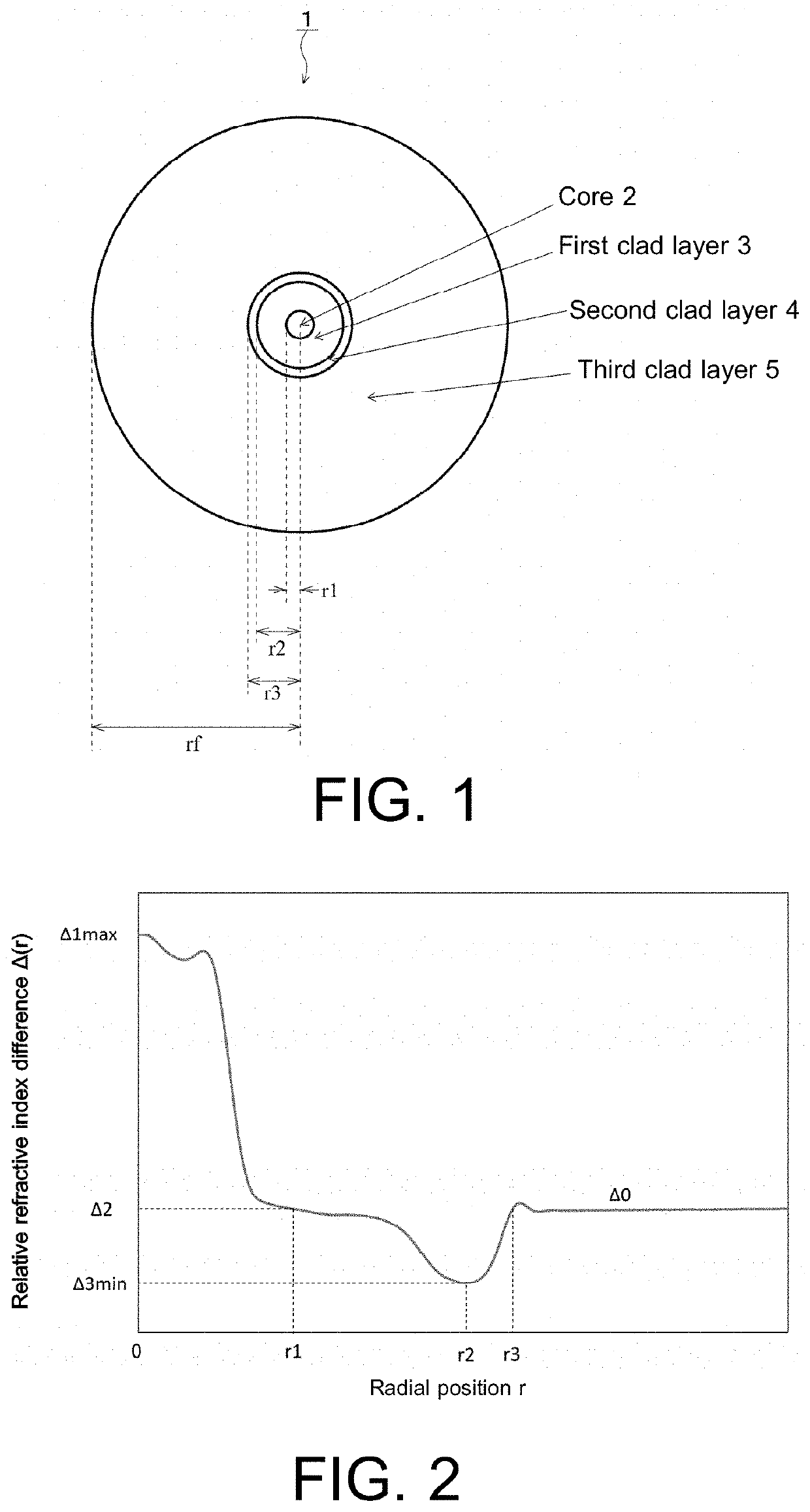
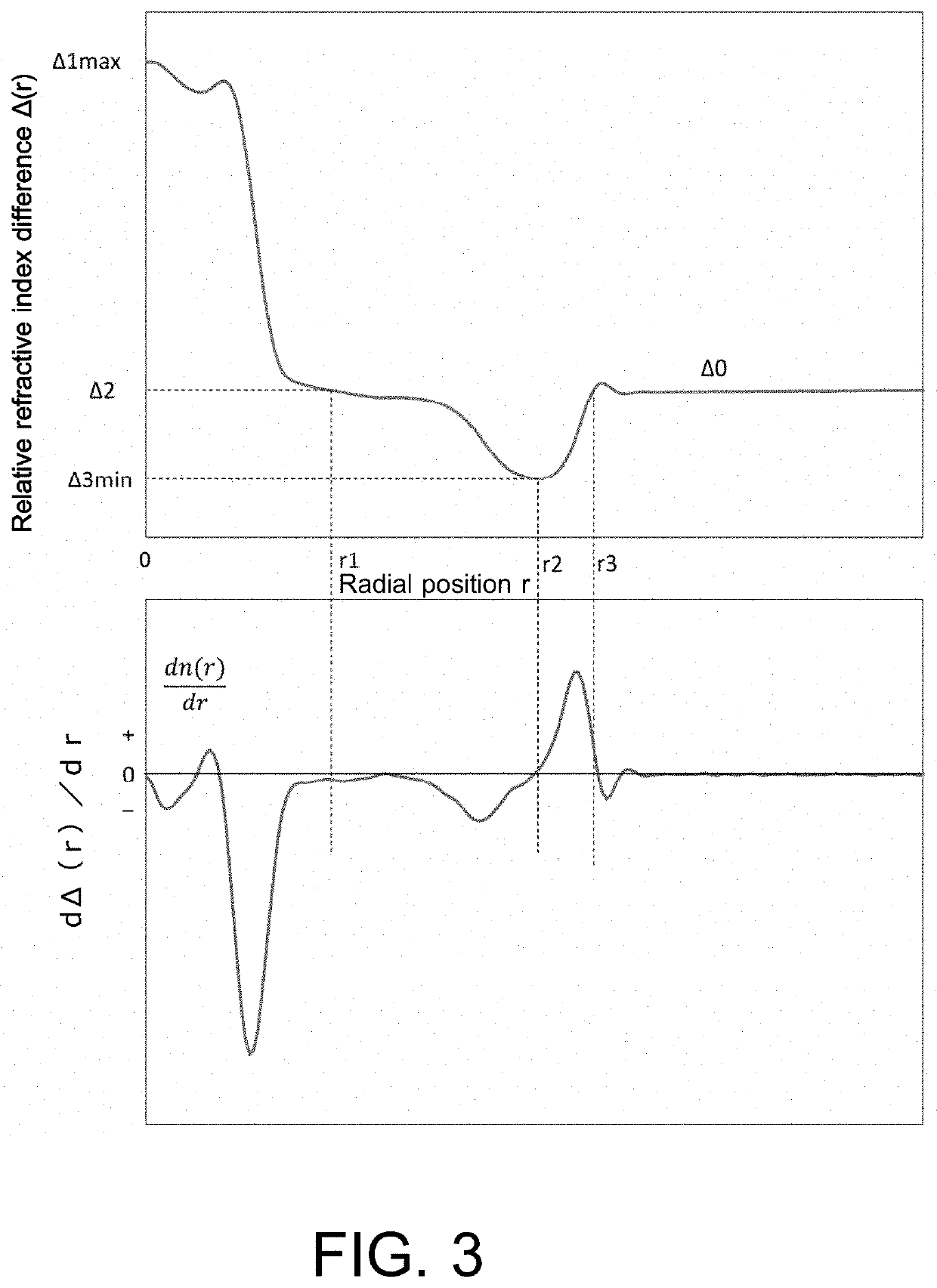
Image

Examples
example 1
[0047]First, a porous glass base material consisting of a core and an intermediate layer was synthesized in one piece by the VAD method. The core was doped with germanium to increase the refractive index. The porous glass base material was heated to about 1200° C. in a mixed gas flow atmosphere of 1 liter per minute of chlorine gas, 0.1 liter per minute of silane tetrafluoride gas, and 20 liters per minute of Ar gas, and the porous glass base material was pulled down at 10 mm / min for dehydration and fluorine doping. Then the porous glass base material was heated to about 1500° C. to make a solid transparent glass core base material. Instead of silane tetrafluoride gas, methane tetrafluoride or ethane hexafluoride may be used.
[0048]This transparent glass core base material was stretched to a predetermined diameter on a glass lathe to make the outer diameters in the longitudinal direction uniform. In this process, though OH groups were incorporated into the surface due to the oxyhydro...
example 2
[0050]First, a porous glass base material consisting of a core and an intermediate layer was synthesized in one piece by the VAD method. The core was doped with germanium to increase the refractive index. The porous glass base material was heated to about 1200° C. in a mixed gas flow atmosphere of 1.5 liters per minute of chlorine gas, 0.12 liter per minute of silane tetrafluoride gas, and 20 liters per minute of Ar gas, and the porous glass base material was pulled down at 10 mm / min for dehydration and fluorine doping. Then, the process of heating the porous glass base material at 1300° C. for 1 hour was added as a process to remove fluorine from the surface. In this process, 20 liters per minute of He flowed. Then the porous glass base material was heated to about 1500° C. to make a solid transparent glass core base material. After that, optical fibers were obtained in the same way as in Example 1.
example 3
[0051]First, a porous glass base material consisting of a core and an intermediate layer was synthesized in one piece by the VAD method. The core was doped with germanium to increase the refractive index. The porous glass base material was heated to about 1200° C. in a mixed gas flow atmosphere of 2.0 liter per minute of chlorine gas, 0.14 liter per minute of silane tetrafluoride gas, and 20 liters per minute of Ar gas, and the porous glass base material was pulled down at 10 mm / min for dehydration and fluorine doping. Then, the process of heating the porous glass base material at 1300° C. for 4 hours was added as a process to remove fluorine from the surface. In this process, 20 liters per minute of He flowed. Then the porous glass base material was heated to about 1500° C. to make a solid transparent glass core base material. After that, optical fibers were obtained in the same way as in Example 1.
PUM
| Property | Measurement | Unit |
|---|---|---|
| bending loss | aaaaa | aaaaa |
| zero-dispersion wavelength | aaaaa | aaaaa |
| length | aaaaa | aaaaa |
Abstract
Description
Claims
Application Information