Optical fiber, slanted optical fiber grating, band rejection optical filter, gain equalizing optical filter for optical amplifier, and optical amplifier module

a technology of optical amplifier and optical fiber, applied in the direction of cladded optical fibre, instruments, optical elements, etc., can solve the problems of difficult to obtain required loss spectrum, unable to achieve spectral smoothness, and obtainable rejection loss is merely 5 db at best, so as to achieve small insertion loss, small bending loss, and small connection loss

Inactive Publication Date: 2005-08-16
THE FUJIKURA CABLE WORKS LTD
View PDF8 Cites 1 Cited by
  • Summary
  • Abstract
  • Description
  • Claims
  • Application Information

AI Technical Summary

Benefits of technology

[0083]Also, by manufacturing a slant optical fiber grating by using an optical fiber such that, in order to equalize a gain peak around 1530 nm band, a loss generating bandwidth BW is 9 nm or shorter, and a product of a ratio l between the core diameter and the diameter of the lower photosensitivity layer of the core and a theoretical cut-off wavelength λc is 0.98 or less, and by manufacturing a slant optical fiber grating by using an optical fiber such that, in order to equalize a gain peak around the 1555 nm band, such that a loss generating bandwidth BW is 15 nm or shorter, and a product of a ratio l between the core diameter and the diameter of the lower photosensitivity layer of the core and a theoretical cut-off wavelength λc is 0.85 or less, and by connecting these slant optical fiber gratings in series, it is possible to realize a gain equalizing optical filter for optical amplifier in which gain of the optical amplifier can be equalized over a wide range of wavelengths.
[0084]By forming a gain equalizing optical filter for optical amplifier such that the slant optical fiber grating containing the optical fiber according to the first aspect for 8.0 μm to 10.0 μm and a relative refractive index difference Δ of 0.40% to 0.55%, a plurality of slant optical fiber gratings are connected in series, and the single mode optical fiber for 1.3 μm transmission use is connected to the both ends of the slant optical fiber grating, it is possible to realize a gain equalizing optical filter for optical amplifier in which the connection loss to a single mode optical fiber for transmission is small, and the gain of the optical amplifier can be equalized over a wide range of wavelengths.
[0085]Also, forming a gain equalizing optical filter for an optical amplifier such that the slant optical fiber grating containing the optical fiber for 8.0 μm to 9.0 μm and a relative refractive index difference Δ of 0.50% to 0.55%, a plurality of slant optical fiber gratings are connected in series, and the dispersion shifted optical fiber is connected to the both ends of the slant optical fiber grating, it is possible to realize a gain equalizing optical filter for optical amplifier in which the connection loss with a dispersion shifted optical fiber for transmission is small, and the gain of the optical amplifier can be equalized over a wide range of wavelengths.
[0086]Also, by forming an optical amplifier module by using a gain equalizing optical filter for optical amplifier according to the present invention, it is possible to realize an optical amplifier module which can generate an amplified light in which a gain is equalized over a wide range of wavelengths.
[0087]Also, in a gain equalizing optical filter for optical amplifier according to the present invention, because the connection loss is small, it is therefore possible to realize an optical amplifier module having a small insertion loss even if it is used as an optical amplifier module.
[0088]Furthermore, because a gain equalizing optical filter for optical amplifier according to the present invention is manufactured by using an optical fiber having a small bending loss, it is possible to realize an optical amplifier module which has a small bending loss when used as an optical amplifier module and which can be organized in a narrow space.

Problems solved by technology

In contrast, there are disadvantages in that a spectral smoothness cannot be obtained because ripples of 0.1 to 5 dB exists in the rejection band at about 0.1 nm period and there is a large reflection.
However, in the long-period grating, it is difficult to obtain required loss spectrum.
Also, there is a disadvantage in that the obtainable rejection loss is merely 5 dB at best even if an optical fiber for specific use is used.
Therefore, the long-period grating is not suitable for gain flattening operation in a broad wavelength bandwidth.
However, because there are a plurality of backward propagating cladding modes 8, it was a general problem in that a loss occurrence wavelength band is broadended.
Therefore, in the optical fiber shown in FIG. 50, it is understood that manufacturing the GEQF having 5 dB of peak loss is difficult.
Thus, this method is not so effective for a purpose of increasing the loss.
Also, if a method such as decreasing the cut-off wavelength is employed, there occurs a trade-off in which the loss increases but bending loss occurs too.
Therefore, there is a limit in this method.

Method used


Image

  • Optical fiber, slanted optical fiber grating, band rejection optical filter, gain equalizing optical filter for optical amplifier, and optical amplifier module
  • Optical fiber, slanted optical fiber grating, band rejection optical filter, gain equalizing optical filter for optical amplifier, and optical amplifier module
  • Optical fiber, slanted optical fiber grating, band rejection optical filter, gain equalizing optical filter for optical amplifier, and optical amplifier module

Examples


Embodiment Construction

[0142]The present invention is explained below in detail.

[0143]An optical fiber according to the present invention comprises a core and a cladding which is disposed around the core, wherein the core contains at least two or more layers having different refractive indexes. The innermost layer is a lower photosensitivity layer of which photosensitivity to a change of refractive index by a light irradiation is lower than a photosensitivity of other layer, the cladding contains at least two or more layers having different refractive indexes, the layer which contacts the core is a higher photosensitivity layer of which photosensitivity to a change of refractive index by a light irradiation is higher than a photosensitivity of other layers.

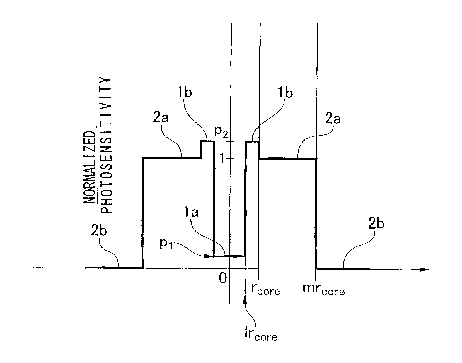
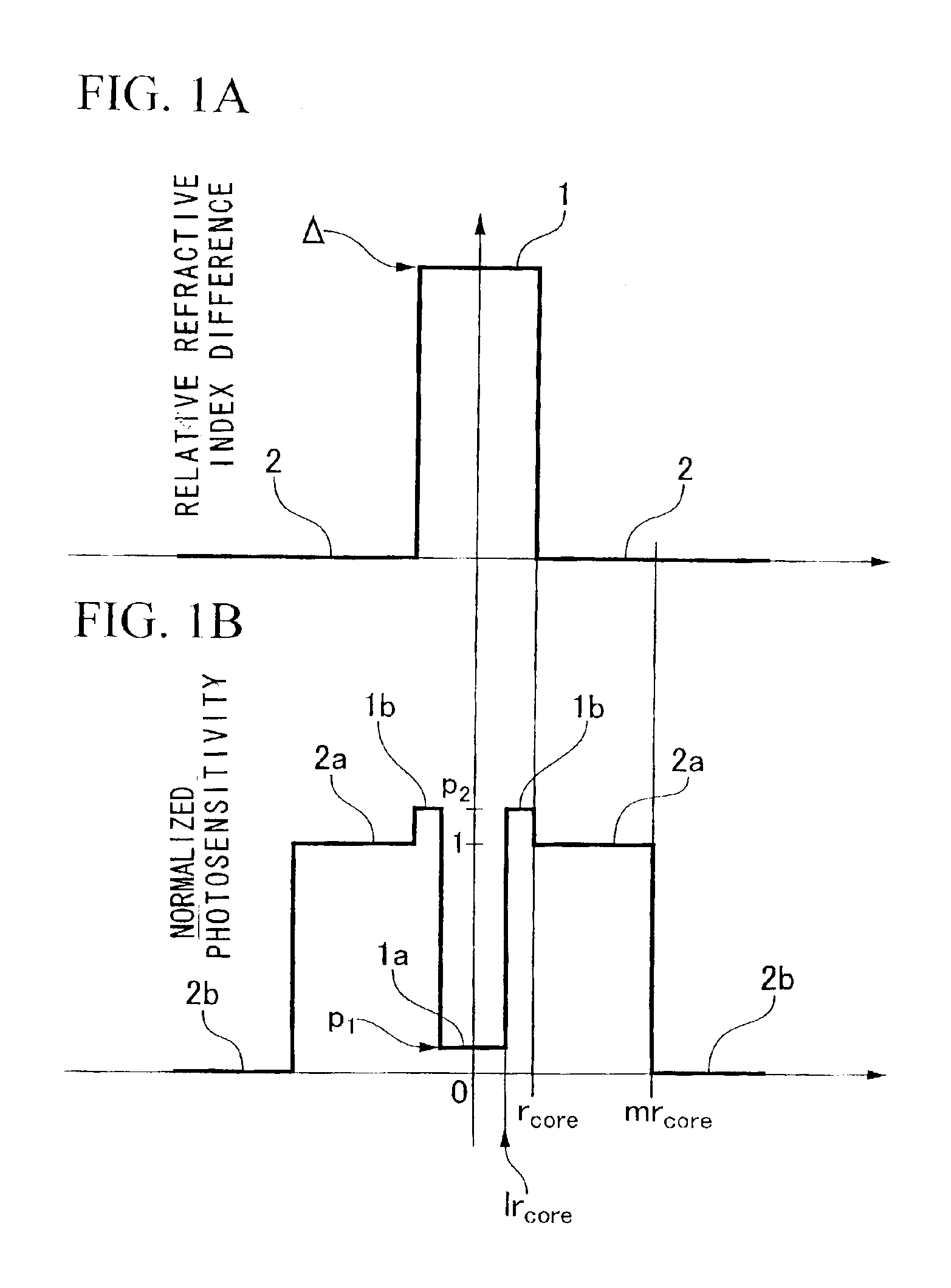
[0144]FIGS. 1A and 1B show an example of the distribution of the refractive index and the photosensitivity of the optical fiber according to the present invention.

[0145]In FIG. 1A, reference numeral 1 indicates a core. Reference numeral 2 indicates a cl...


PUM

PropertyMeasurementUnit
cut-off wavelength λcaaaaaaaaaa
slant angleaaaaaaaaaa
diameteraaaaaaaaaa

Abstract

Photosensitivity of an inner core which is disposed in a central portion of a core is low. Photosensitivity of an outer core which is disposed close to a cladding is high. In the cladding, photosensitivity of the inner cladding which is close to the core is high and photosensitivity of an outer cladding which is outside of the inner cladding is low. A plurality of slant optical fiber grating having different optical characteristics by using the optical fiber having such photosensitivity so as to form a gain equalizing optical filter. By doing this, it is possible to provide an optical filter having a slant optical fiber grating which can maintain a filtering characteristics in a narrow bandwidth and enlarge loss area.

Description

BACKGROUND OF THE INVENTION[0001]1. Field of the Invention[0002]The present invention relates to an optical fiber component which is used for optical communication and optical information processing. In particular, the present invention relates to an optical filter for improving wavelength dependence of the gain of an optical amplifier containing an Erbium-doped optical fiber (hereinafter called EDFA) so as to perform gain flattening operation and gain equalizing operation. Also the present invention relates to an optical fiber which is used for the optical filter.[0003]2. Description of Related Art[0004]An optical fiber grating which has a periodic refractive index modulation in a longitudinal direction of the optical fiber by utilizing an increase of the refractive index of a Ge-doped section in a silica optical fiber by irradiating with ultraviolet light has advantages such as low inserttion loss, low manufacturing cost, and high reliability. Because of these advantages, the opti...

Claims


Application Information

Patent Timeline
Patent Type & Authority Patents(United States)
IPC IPC(8): G02F1/39G02B6/02G02B6/34G02F1/35
CPCC03C3/06C03C13/00G02B6/02119G02B6/0365G02B6/03694G02B6/0208
Inventor SUDO, MASAAKINIWA, ATUHIKOOKUDE, SATOSHI
Owner THE FUJIKURA CABLE WORKS LTD
Why Eureka
Try Eureka