

Kneading apparatus
a technology of kneading apparatus and kneading blade, which is applied in the direction of mechanical apparatus, piston rings, engine components, etc., can solve the problems of reducing the kneading efficiency, and achieve the effects of reducing molding time, preventing drying, and enhancing kneading efficiency
- Summary
- Abstract
- Description
- Claims
- Application Information
AI Technical Summary
Benefits of technology
Problems solved by technology
Method used
Image

Examples
first embodiment
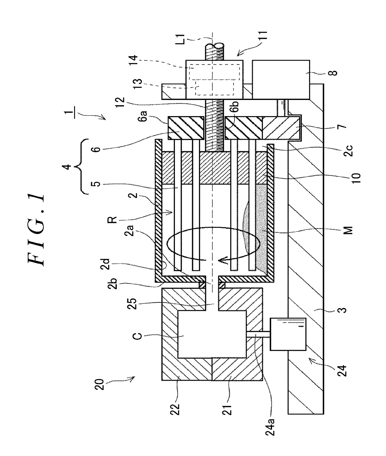
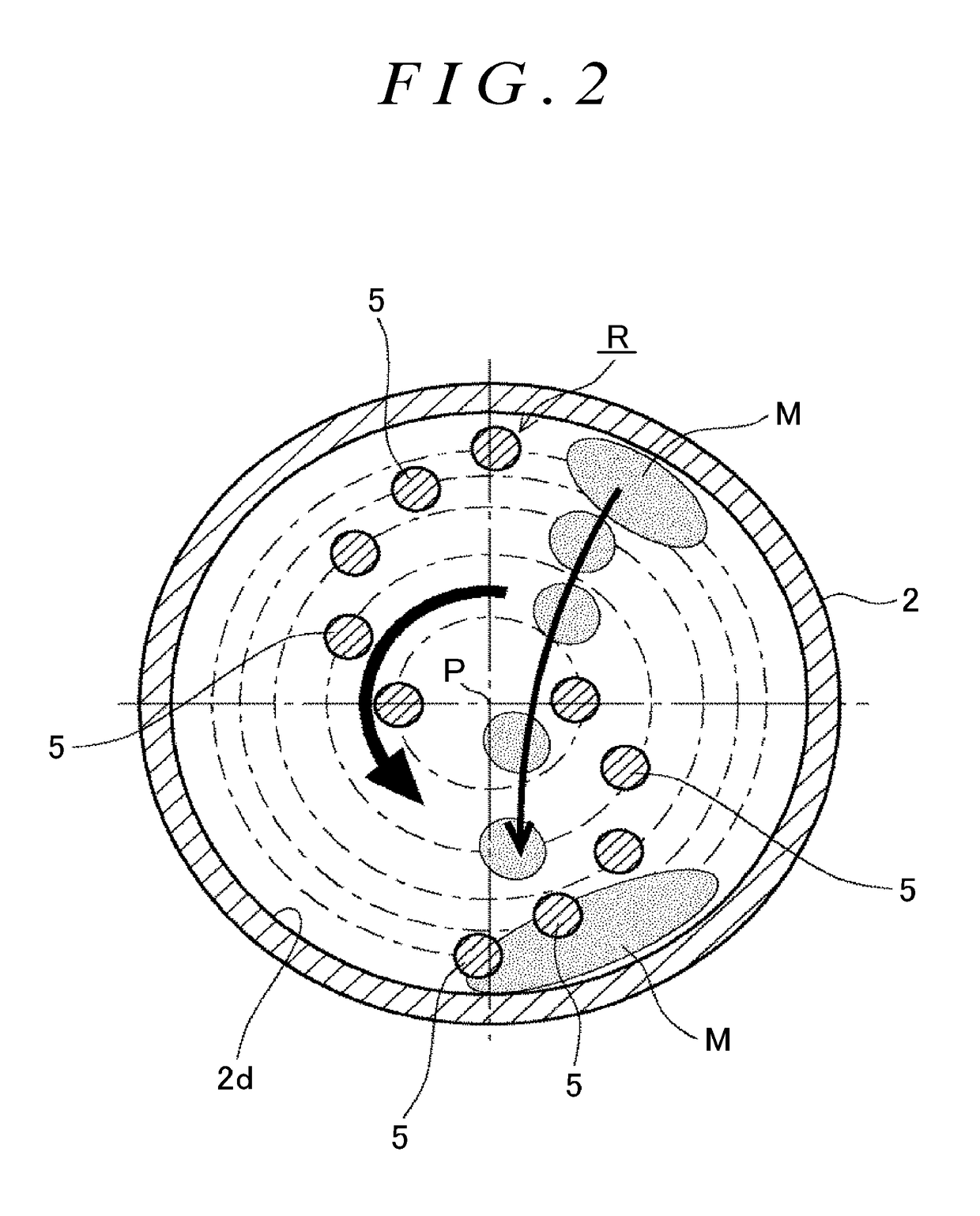
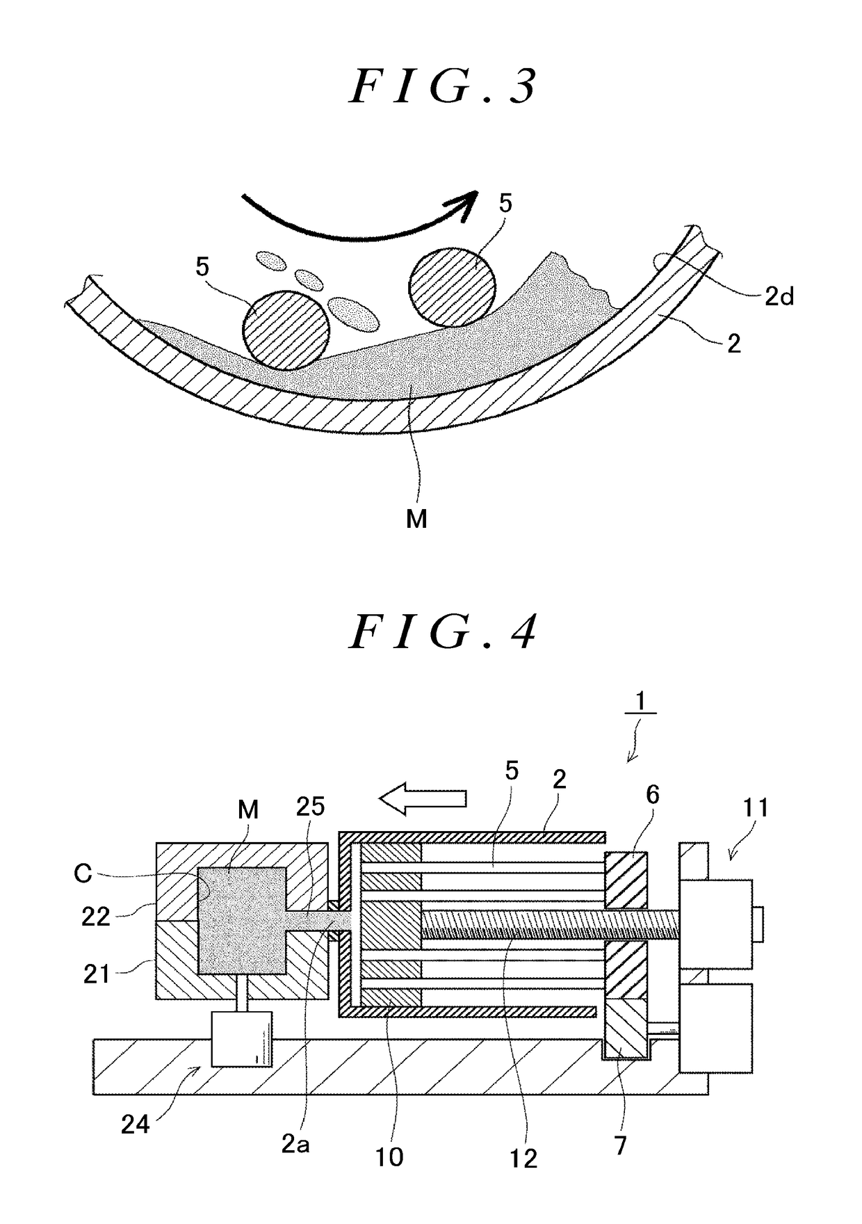
[0031][First Embodiment ]As shown in FIG. 1, a kneading apparatus 1 kneads together artificial sand, soluble glass, and an additive. An inorganic core is manufactured with a kneaded material M. The kneading apparatus 1 has a cylindrical kneading vessel 2, and the kneading vessel 2 is fixed on an installation stand 3 and extends in the horizontal direction. An agitator 4 is disposed inside the kneading vessel 2, and as the agitator 4 rotates, the material M can be kneaded inside the kneading vessel 2.
[0032]The agitator 4 includes a plurality of (e.g., ten) agitating pins 5 that rotate around a rotation axis L1 of the agitator 4 extending in the horizontal direction and that extend in the horizontal direction inside the kneading vessel 2, and a rotation base 6 provided on the base end side of the agitating pins 5. The rotation base 6 has the agitating pins 5 fixed thereon and a gear part 6a formed on the outer periphery. The rotation base 6 is disposed on the side of an opening 2c of ...
second embodiment
[0041][Second Embodiment ]A kneading apparatus 30 will be described. Those components that are the same as or equivalent to the components of the first embodiment will be given the same reference signs and repeated description thereof will be omitted.
[0042]As shown in FIG. 6, the kneading apparatus 30 is used to knead together artificial sand, soluble glass, and an additive. An inorganic core is manufactured with the kneaded material M. The kneading apparatus 30 has a cylindrical kneading vessel 32, and the kneading vessel 32 is fixed on an installation stand 33 and extends in the horizontal direction. The agitator 4 is disposed inside the kneading vessel 32, and as the agitator 4 rotates, the material M can be kneaded through cooperation between the agitator 4 and an inner wall surface 32d of the kneading vessel 32.
[0043]As in the first embodiment, the agitator 4 includes the plurality of agitating pins 5 that are arrayed in an S-shape or an inverted S-shape to be symmetric with r...
third embodiment
[0046][Third Embodiment ]A kneading apparatus will be described. Those components that are the same as or equivalent to the components of the first embodiment will be given the same reference signs and repeated description thereof will be omitted. The third embodiment can also be implemented in the substantially same configuration as that of the second embodiment.
[0047]The kneading apparatus of this embodiment is configured such that the agitating pins rotate. As shown in FIG. 7, in a kneading apparatus 40, a rotation base 41 is rotated by a motor (not shown), and on the basis of the rotation of the rotation base 41, agitating pins 42 revolve around the rotation axis L1 and at the same time rotate around rotation axes L2 of the agitating pins 42. FIG. 7 is a simplified view in which the injection piston 10 etc. are omitted to clarify the configuration of the agitator. Here, the agitating pins 42 of this embodiment are disposed around the rotation axis L1 at 90° intervals in the rot...
PUM
| Property | Measurement | Unit |
|---|---|---|
| diameter | aaaaa | aaaaa |
| rotation | aaaaa | aaaaa |
| speed | aaaaa | aaaaa |
Abstract
Description
Claims
Application Information