Heavy duty pneumatic tire

a technology of pneumatic tires and heavy duty, applied in the direction of tyre tread bands/patterns, vehicle components, transportation and packaging, etc., can solve the problems of deteriorating on-snow performance, high friction, and congestion of space between adjacent projected portions, so as to improve uneven wear resistance, prevent excessive deformation of the central, and improve uneven wear resistance

Active Publication Date: 2019-03-19
SUMITOMO RUBBER IND LTD
View PDF12 Cites 2 Cited by
  • Summary
  • Abstract
  • Description
  • Claims
  • Application Information

AI Technical Summary

Benefits of technology

[0064]Furthermore, when the edge 33a of the first end portion 21 receives a lateral force from the compressed snow in the central main groove 4, the first end portion 21 is elastically deformed so that the first projected portion 26 further protrudes into the central main groove 4. Accordingly, the first projected portion 26 may further compress the snow introduced in the central main groove 4 so that a large shearing force may be obtained. Subsequently, as the first end portion 21 is released from the contact patch, the compressed snow held by the first projected portion 26 will also be released away from the main groove. This action may be useful to prevent clogging the central main groove 4. It is understood for the person skilled in the art that the same advantageous effects may be brought on the second end portion 22.
[0065]FIG. 5 illustrates an enlarged view of the central portion 10 in accordance with another embodiment of the invention. As shown in FIG. 5, the central lateral groove 14 may be provided with a tie-bar 40 in which the bottom is raised. The tie-bar 40 may prevent excessive deformation of the central blocks 15 to improve uneven wear resistance.
[0066]FIG. 6 illustrates a cross-sectional view taken along lines B-B of FIG. 5. As shown in FIG. 6, the central lateral groove 14 has a depth d5 at the tie-bar 40 in a range of from 0.4 to 0.6 times the maximum depth b4 of the central lateral groove 14 in order to improve uneven wear resistance while ensuring on-snow performance as well as wet performance. Referring back to FIG. 5, the tie-bar 40 extends along the central lateral groove 14 so as to cross the extension line 32 of one of the side edges 36 of the middle portion 24. Such a tie-bar 40 may be useful to improve edge effect of the first and second projected portions 26 and 27.
[0067]In order to further improve the advantageous effects, an axial protruding length L1 of the tie-bar 40 from the extension line 32 at the edge 33 of the central block 15 is in a range of not less than 0.2 times, more preferably not less than 0.4 times, but preferably not more than 0.8 times, more preferably not more than 0.6 times an axial width W11 from the corner 39 of the first projected portion 27 to an intersection 43 where the extension line 32 crosses the edge 33 of the central block 15.
[0068]As shown in FIG. 2, the central portion 10 is preferably formed as a second block row that comprises the first blocks 41 only. This may help to prevent bias traveling of the vehicle.
[0069]Preferably, in a pair of central blocks 15 which are circumferentially adjacent, a pair of the first projected portions 26 and 26 may be adjacent through one of the central lateral grooves 14 in order to further improve on-snow traction by compressing the snow strongly between adjacent projected portions. In another aspect of the invention, a pair of the second projected portions 27 and 27 may be adjacent through one of the central lateral grooves 14.

Problems solved by technology

Each edge of the portions of the block may produce high friction force against icy road by scratching the road.
Unfortunately, since the respective projected portions are located on the same side and closely in the circumferential direction of the tire, the space between adjacent projected portions tends to be clogged up with snow during traveling.
This may cause a problem of deteriorating of on-snow performance as well as deteriorating of wet performance.

Method used


Image

  • Heavy duty pneumatic tire
  • Heavy duty pneumatic tire
  • Heavy duty pneumatic tire

Examples


example

Example 1

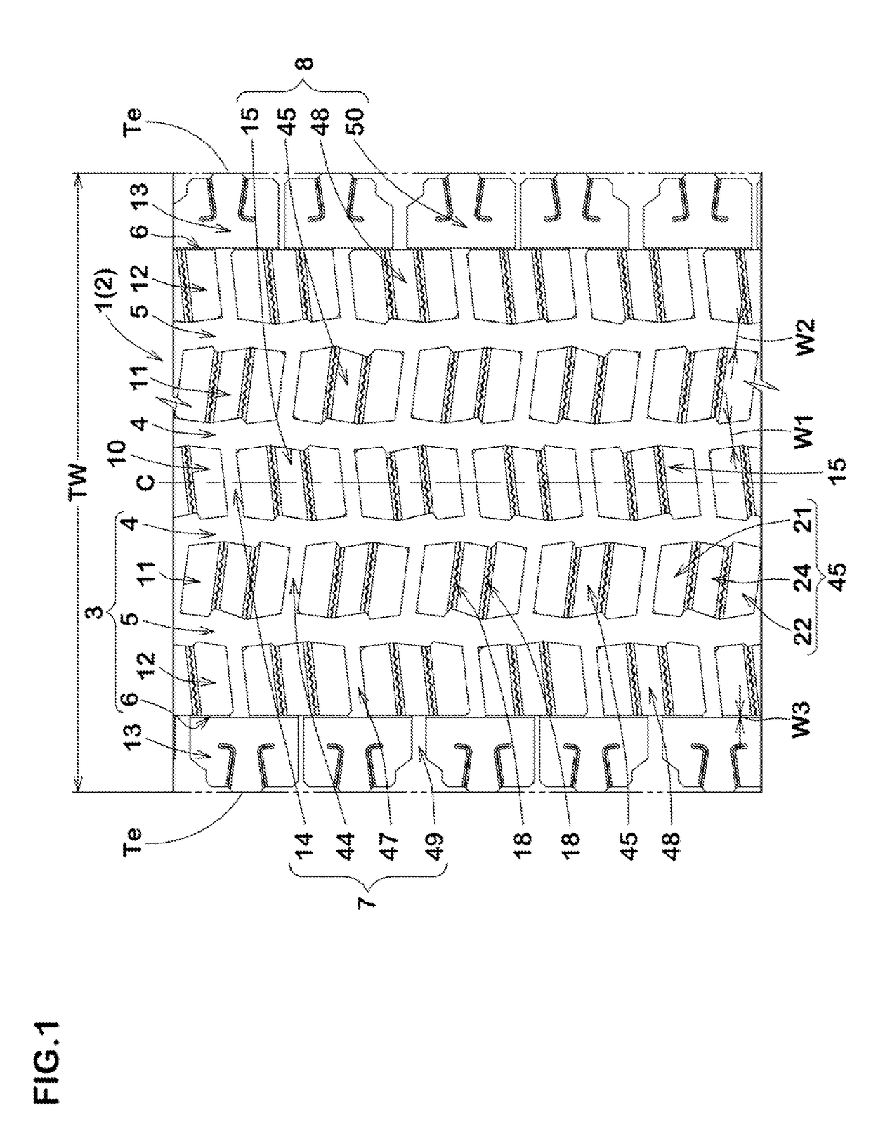
[0088]Heavy duty pneumatic tires having a size of 11R22.5 and the tread pattern shown in FIGS. 1 and 9 were manufactured based on the details of Table 1, and then on-snow performance and wet performance thereof were tested. The common specifications of tires and test procedures are as follows.

[0089]Rim size: 8.25×22.5

[0090]Internal pressure: 900 kPa

[0091]Test vehicle: a 10 ton truck with a 5 ton load on its front side of the platform

[0092]Tire installing location: all wheels

On-Snow Performance Test:

[0093]The above mentioned test vehicle was made to run on snowy road and then the driver evaluated the traveling performance by his feeling. The test results were shown using a score based on Ref. 1 being 100. The larger the value, the better the wet performance is.

Wet Performance Test:

[0094]The test driver suddenly started the above mentioned test vehicle using the second gear position by engaging its clutch at the timing of a 1,500 rpm engine speed on a wet asphalt road with a ...

example 2

[0097]Heavy duty pneumatic tires having a size of 11R22.5 and the tread pattern shown in FIGS. 1 and 9 were manufactured based on the details of Table 2, and then on-snow performance, wet performance and wear resistance thereof were tested. The common specifications of tires and the test procedures of on-snow and wet performance are the same as the mentioned above. The wear resistance test is as follows.

Wear Resistance Test:

[0098]The test vehicle was made to run on a dry asphalt test course for a certain distance and then the amount of average wear of the central blocks was measured. The results were indicated using an index beaded on Ref. 1 being 100. The smaller the value, the better the performance is.

[0099]The test results are shown in Table 2. From the test results, it was confirmed that Example tires in accordance with the present invention can be improved on-snow and wet performance in a well balanced manner.

[0100]

TABLE 2Ref. 1Ex. 1Ex. 2Ex. 3Ex. 4Ex. 5Ex. 6Ex. 7Ex. 8Ex. 9Ex. ...


PUM


Abstract

A heavy duty pneumatic tire includes a tread portion including a plurality of blocks separated by a plurality of circumferentially extending main grooves and a plurality of lateral grooves. At least one of the blocks is provided with two axially extending sipes to divide the block into a first end portion, a second end portion and a middle portion between the first end portion and the second end portion. The first end portion includes a first projected portion that protrudes outwardly in a block-width direction from the middle portion so as to form a steplike side, and the second end portion includes a second projected portion that protrudes outwardly in an opposite block-width direction to the first projected portion from the middle portion so as to form a steplike side.

Description

BACKGROUND OF THE INVENTION[0001]Field of the Invention[0002]The present invention relates to heavy duty pneumatic tires, and in particular, relates to a heavy duty pneumatic tire that may exhibit an excellent wet performance as well as on-snow performance.[0003]Description of the Related Art[0004]Japanese Unexamined Patent Application Publication No. 2005-280457 discloses a heavy duty pneumatic tire including a tread portion provided with a plurality of tread blocks separated by circumferentially extending main grooves and lateral grooves. Each tread block is provided with two axially extending sipes to divide the block into three portions which includes a pair of end portions and a middle portion therebetween. Each edge of the portions of the block may produce high friction force against icy road by scratching the road. Furthermore, each of the end portions of the block includes a projected portion that protrudes outwardly in a block-width direction from the middle portion. The re...

Claims


Application Information

Patent Timeline
Patent Type & Authority Patents(United States)
IPC IPC(8): B60C11/11B60C11/13B60C11/03B60C11/12B60C11/04
CPCB60C11/0327B60C11/0306B60C11/042B60C11/12B60C11/125B60C11/1369B60C11/11B60C2011/1213B60C11/0311B60C11/032
Inventor MATSUDA, KAE
Owner SUMITOMO RUBBER IND LTD
Why Eureka
Try Eureka