Vehicle

a technology for vehicles and housing tubes, applied in the field of vehicles, can solve the problems of reducing the possibility of heat transfer from the exhaust manifold, affecting the operation of vehicles, so as to achieve the effect of suppressing damage to the accommodating tub

Inactive Publication Date: 2019-03-19
TOYOTA JIDOSHA KK
View PDF10 Cites 0 Cited by
  • Summary
  • Abstract
  • Description
  • Claims
  • Application Information

AI Technical Summary

Benefits of technology

[0007]The inventor investigated, in a vehicle in which a wire harness is located on a side of a heat insulator, the state of the wire harness in the case in which a considerable force acted around an internal combustion engine daring a vehicle collision or the like, and found that damage to the wire harness was caused by sliding movement of an end edge of the heat insulator. In the above configuration, the end edge among the end edges of the heat insulator has the shape that is protruding and recessed in the plate thickness direction in the side view of the end edge, the end edge being located on the side of the wire harness. Thus, when the wire harness interferes with the end edge of the heat insulator, the position where the end edge slides changes in the plate thickness direction. As a result, as compared to a configuration in which the end edge is formed to be linear (straight) in a side view thereof, the sliding position can be dispersed and the sliding distance (the distance by which the end edge slides) in one place on the wire harness can be shortened. Thus, with the above configuration, it is possible to suppress damage to the wire harness caused by sliding movement of the end edge of the heat insulator.
[0009]In the above configuration, in the end edge of the heat insulator, the distance in the plate thickness direction between the outer end face of the recessed portion of the end edge and the distal end face of the protruding portion of the end edge is longer than the length between the large-diameter portions adjacent to each other in the accommodating tube. In other words, the height of the protruding and recessed portions in the end edge of the heat insulator is longer than the length of each of the small-diameter portions in an axial direction of the accommodating tube. Thus, when the end edge of the heat insulator slides on the small-diameter portion of the accommodating tube and their relative positions are changed, the protruding portion of the end edge of the heat insulator contacts (engages with) the large-diameter portion of the accommodating tube. Accordingly, the contact area Between the heat insulator arid the accommodating tube increases and the sliding movement thereof is suppressed. Thus, it is possible to further suppress damage to the accommodating tube of the wire harness.
[0011]In the end edge of the heat insulator, a connecting face that connects the outer end face of the recessed portion with the distal end face of the protruding portion extends in the plate thickness direction. In the above configuration, the length, in the direction perpendicular to the plate thickness direction, of the outer end face of the recessed portion and the length, in the direction perpendicular to the plate thickness direction, of the distal end face of the protruding portion is shorter than the diameter of each of the small-diameter portions of the accommodating tube in the side view. Therefore, an interval between the pro trading and recessed portions in the end edge of the heat insulator is short, and thus, the connecting face that connects, the outer end face with the distal end face contacts the accommodating tube when the small-diameter portion or the large-diameter portion of the accommodating tube contacts the end edge of the heat insulator. Because the connecting face extends in the plate thickness direction, the area of contact between the accommodating tube and the heat insulator at a given moment can be widened in the axial direction of the accommodating tube. Thus, when the end edge of the heat insulator slides on the accommodating tube, a load applied to the accommodating tube can be dispersed in the axial direction. Accordingly, as compared to the case where a load is locally concentrated, damage to the accommodating tube can be suppressed.

Problems solved by technology

The heat insulator reduces the possibility that heat released from the exhaust manifold is transferred to other components that are disposed around the internal combustion engine.
In the case where a considerable force acts around the internal combustion engine during a vehicle collision or the like, the relative positions of the heat insulator and the wire harness may be changed and they may interfere with each other.
As a result, the wire harness may be damaged.
As described above, when the heat insulator interferes with other components that are disposed around the heat insulator, the other components may be damaged.
However, there is no disclosure about such points in JP 2011-149338 A, and vehicles including a heat insulator still have room for improvement.
The inventor investigated, in a vehicle in which a wire harness is located on a side of a heat insulator, the state of the wire harness in the case in which a considerable force acted around an internal combustion engine daring a vehicle collision or the like, and found that damage to the wire harness was caused by sliding movement of an end edge of the heat insulator.

Method used


Image

  • Vehicle
  • Vehicle
  • Vehicle

Examples


first embodiment

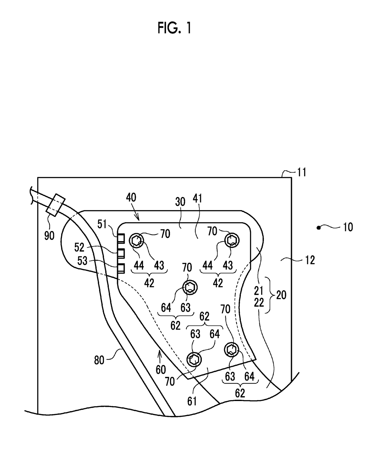
[0020]a vehicle is described with reference to FIG. 1 to FIG. 4. As shown in FIG. 1, an internal combustion engine 11 is mounted in an engine compartment 10 of the vehicle. An exhaust manifold 20 as an exhaust component is connected to a cylinder head 12 of the internal combustion engine 11. Exhaust gas that is discharged from combustion chambers of the internal combustion engine 11 is introduced into the exhaust manifold 20 through exhaust ports (not shown) that are formed in the cylinder head 12. The exhaust manifold 20 includes a branch pipe portion 21 on the exhaust upstream side and a junction pipe portion 22 that is connected to the exhaust downstream side of the branch pipe portion 21. The branch pipe portion 21 is branched at an upstream end, and each of the branched ends is connected to a corresponding one of the exhaust ports. A heat insulator 30 is connected to the exhaust manifold 20.

[0021]The heat insulator 30 is formed of a metal plate material, and has a three-dimensi...

second embodiment

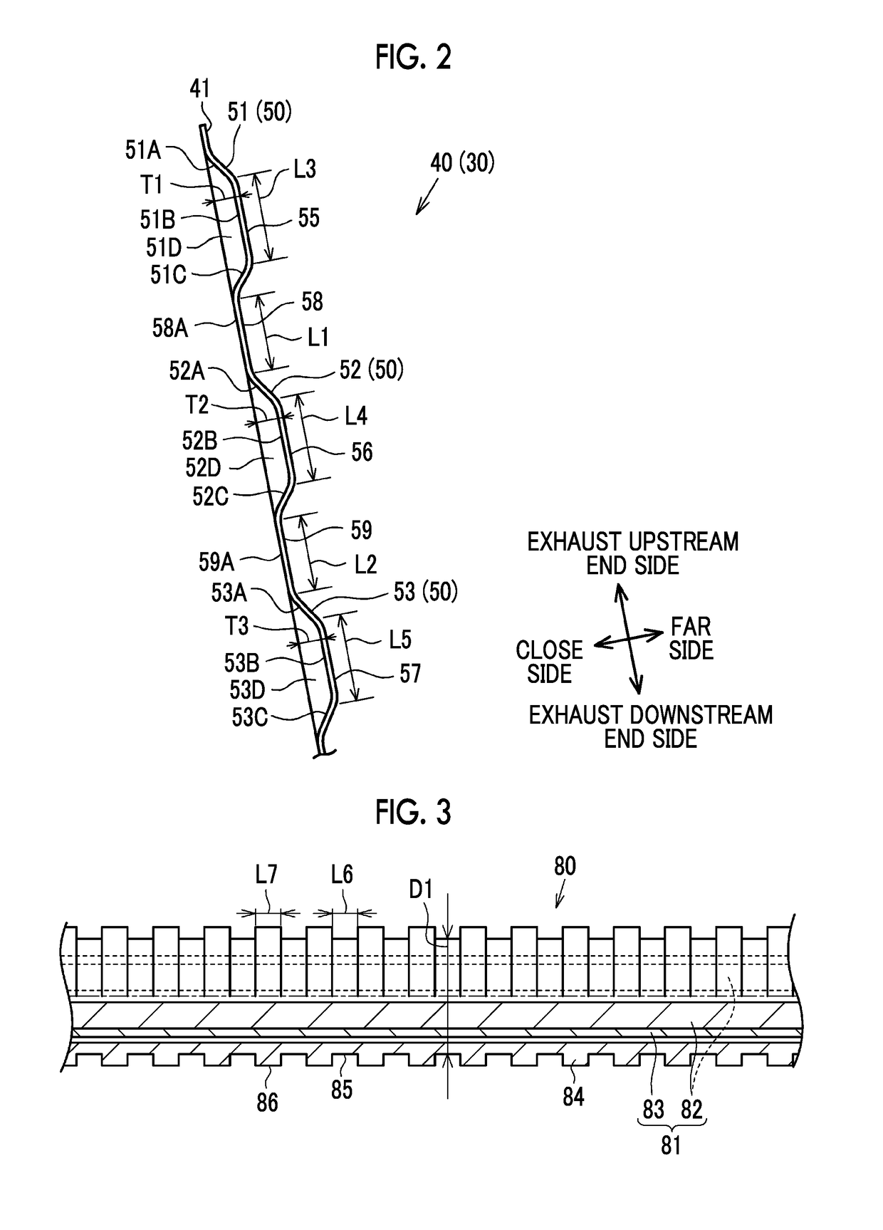
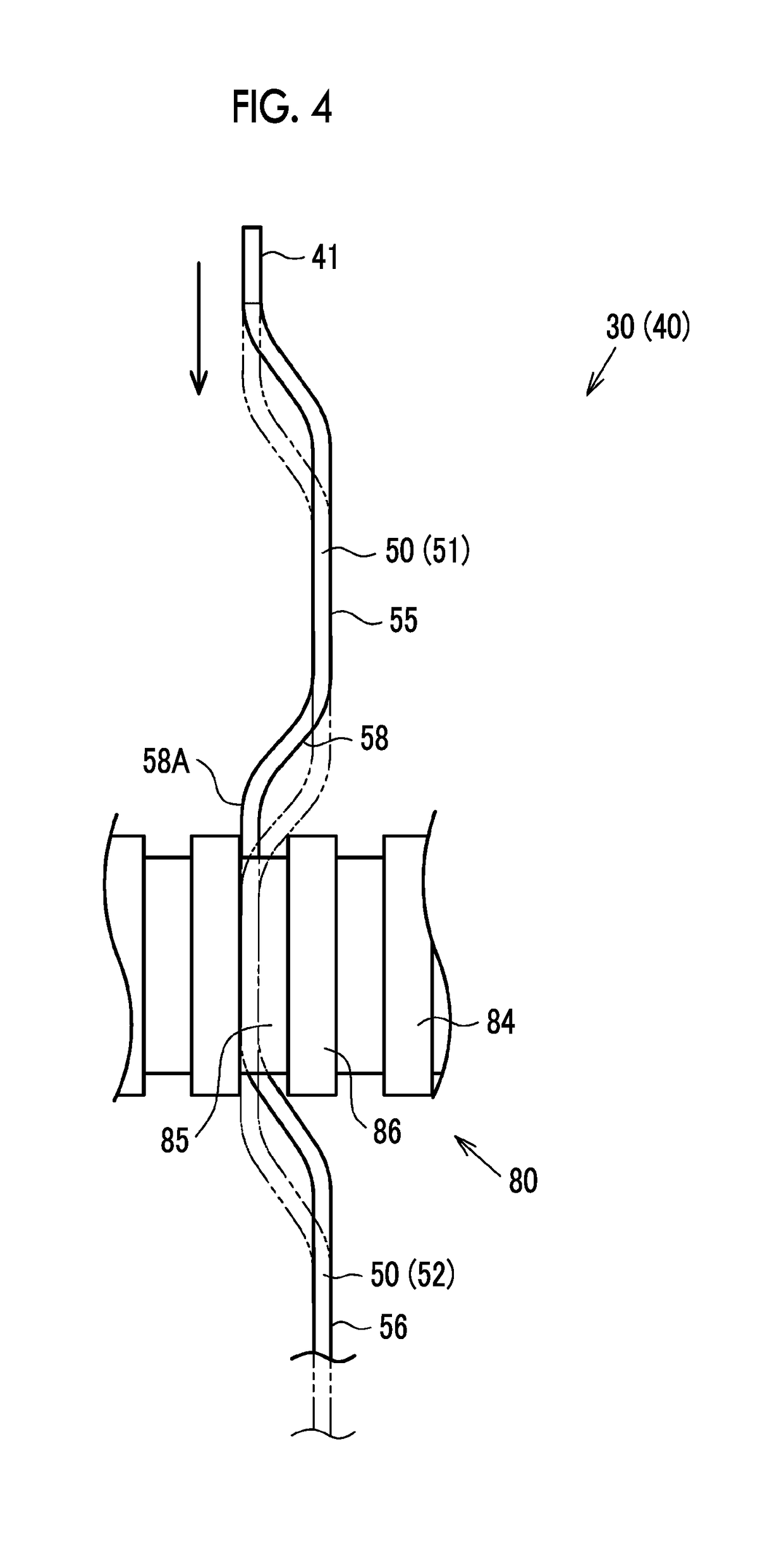
[0047] the following effects can be obtained in addition to the effect as described in above (1). (4) In the end edge of the heat insulator, the end edge being is located on the side of the wire harness 80, the inclined walls 151C, 152A, 152C, and 153A as the connecting feces that connect the outer end faces 158A and 159A of the recessed portions 158 and 159 with the distal end faces 155, 156, and 157 of the protruding, portions 150 extend in the plate thickness direction. In this embodiment, the lengths L11 and L12, in the perpendicular direction, of the outer end faces 158A and 159A of the recessed portions 158 and 159, and the lengths L13, L14, and L15, in the direction perpendicular to the plate thickness direction, of the distal end faces 155, 156, and 157 of the protruding portions 150 are shorter than the diameter D1 of the small-diameter portion 85 of the accommodating tube 84.

[0048]As shown in FIG. 6, in the end edge of the heat insulator 130, an interval A1 between the pro...


PUM


Abstract

A vehicle includes a heat insulator in a form of a plate, the heat insulator covering an exhaust component of an internal combustion engine; and a wire harness disposed on a side of the heat insulator. An end edge among end edges of the heat insulator has a shape that is protruding and recessed in a plate thickness direction in a side view of the end edge, the end edge being located on a side of the wire harness.

Description

CROSS-REFERENCE TO RELATED APPLICATIONS[0001]The present application claims priority to Japanese Patent Application No. 2016-245815 filed on Dec. 19, 2016, which is incorporated herein by reference in its entirety including the specification, drawings and abstract.BACKGROUND1. Technical Field[0002]The disclosure relates to a vehicle.2. Description of Related Art[0003]Japanese Patent Application Publication No. 2011-149338 (JP 2011-149338 A) discloses a heat insulator provided in a vehicle. The heat insulator is formed of a metal plat(c) material. The heat insulator has a three-dimensional shape that conforms to the external shape of an exhaust manifold of an internal combustion engine. The heat insulator is disposed to cover the exhaust manifold. The heat insulator reduces the possibility that heat released from the exhaust manifold is transferred to other components that are disposed around the internal combustion engine.SUMMARY[0004]In a vehicle, a wire harness is routed and dispo...

Claims


Application Information

Patent Timeline
Patent Type & Authority Patents(United States)
IPC IPC(8): B60R16/02B60R13/08
CPCB60R13/0869B60R16/0215B60R13/0876F01N13/14F02B77/11
Inventor NAKAO, HITOSHI
Owner TOYOTA JIDOSHA KK
Why Eureka
Try Eureka