Eureka AIR delivers breakthrough ideas for toughest innovation challenges, trusted by R&D personnel around the world.

Reflex sight with two position-adjustable reticles

Active Publication Date: 2019-03-19
GARMIN INT
View PDF7 Cites 5 Cited by
  • Summary
  • Abstract
  • Description
  • Claims
  • Application Information

AI Technical Summary

Benefits of technology

The present invention is a reflex sight that addresses various limitations of existing reflex sights. The reflex sight has a mounting base that can be attached to a firearm and a collimating front lens. It also has two reticulums, one of which is adjustable in elevation and the other of which is adjustable in a wider field of view. The reflex sight can display a pattern of reticles that adjust to cover different angular areas in the field of view, based on the prior knowledge of an aiming point range. The invention addresses the problem of limited visibility in low-light conditions and provides improvements in targeting accuracy.

Problems solved by technology

Also, there is a fair amount of uncertainty in the angle at which a projectile will leave the weapon, or for a shotgun, the area over which pellets will hit.
There are currently limited options for assisting a shooter in forming an estimate of an area over which a projectile is likely to hit, or shotgun pellets will hit.
Conversely, there are limited options for determining where a bullet will quite certainly not hit, so that it may be difficult at times to estimate potential collateral damage.

Method used


Image

  • Reflex sight with two position-adjustable reticles
  • Reflex sight with two position-adjustable reticles
  • Reflex sight with two position-adjustable reticles

Examples


Embodiment Construction

Definition

[0021]“Ordinance Spread” in the context of a single projectile weapon, such as a handgun or a crossbow, is the angular area over which a projectile may hit, due to uncertainty as to the projectile launch. In the context of a multi-projectile weapon, such as a shotgun, it is the area of which projectiles (shot) are likely to hit.

Description

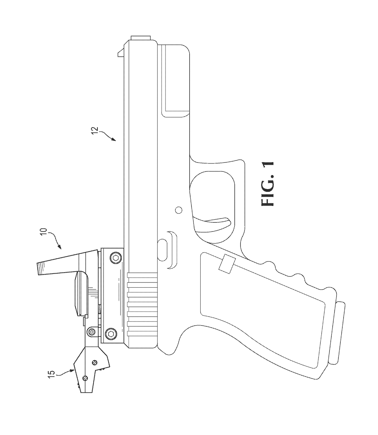
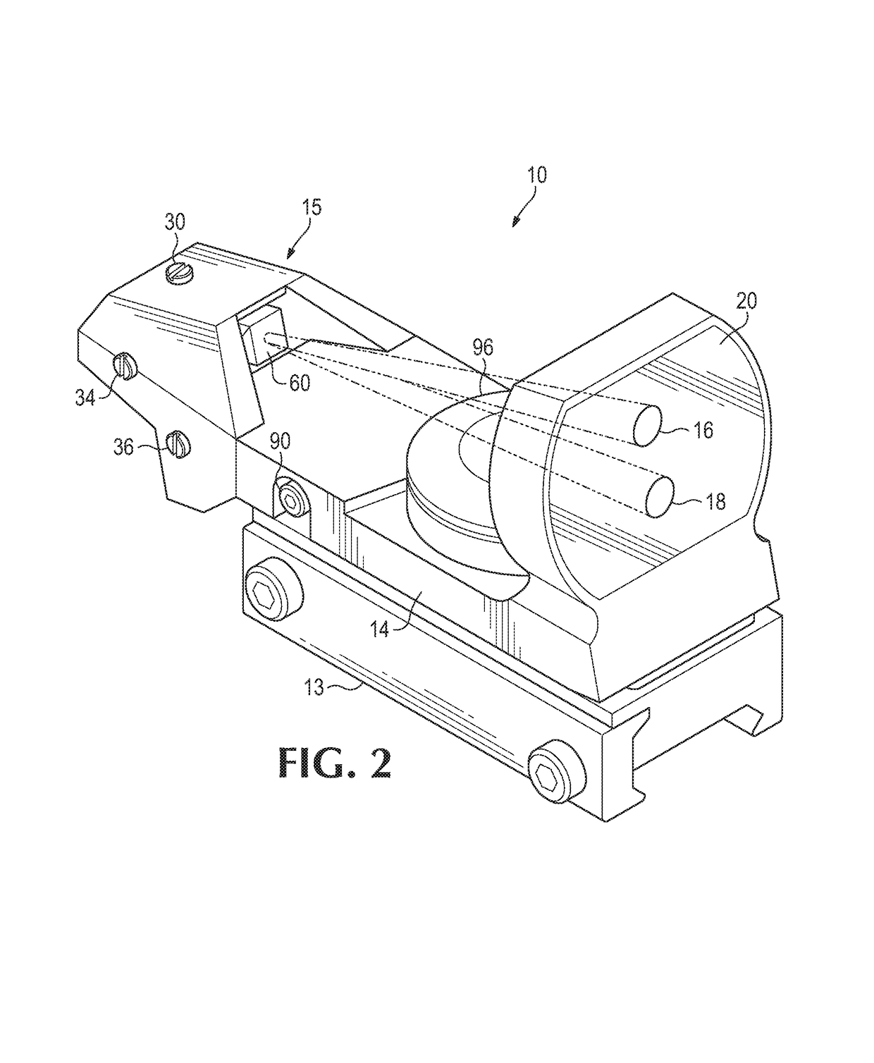
[0022]Referring to FIG. 1, a reflex sight 10, according to a preferred embodiment of the present invention, is shown attached to a handgun 12 by a base 13. FIG. 2 shows an upper frame 14, supporting a reticle projection assembly 15 projecting a first reticle 16, and a second reticle 18, onto a front collimating lens 20. A collimating lens renders parallel the rays of light passing through it, in this case from front to back. This removes parallax from a user's field of view through lens 20.

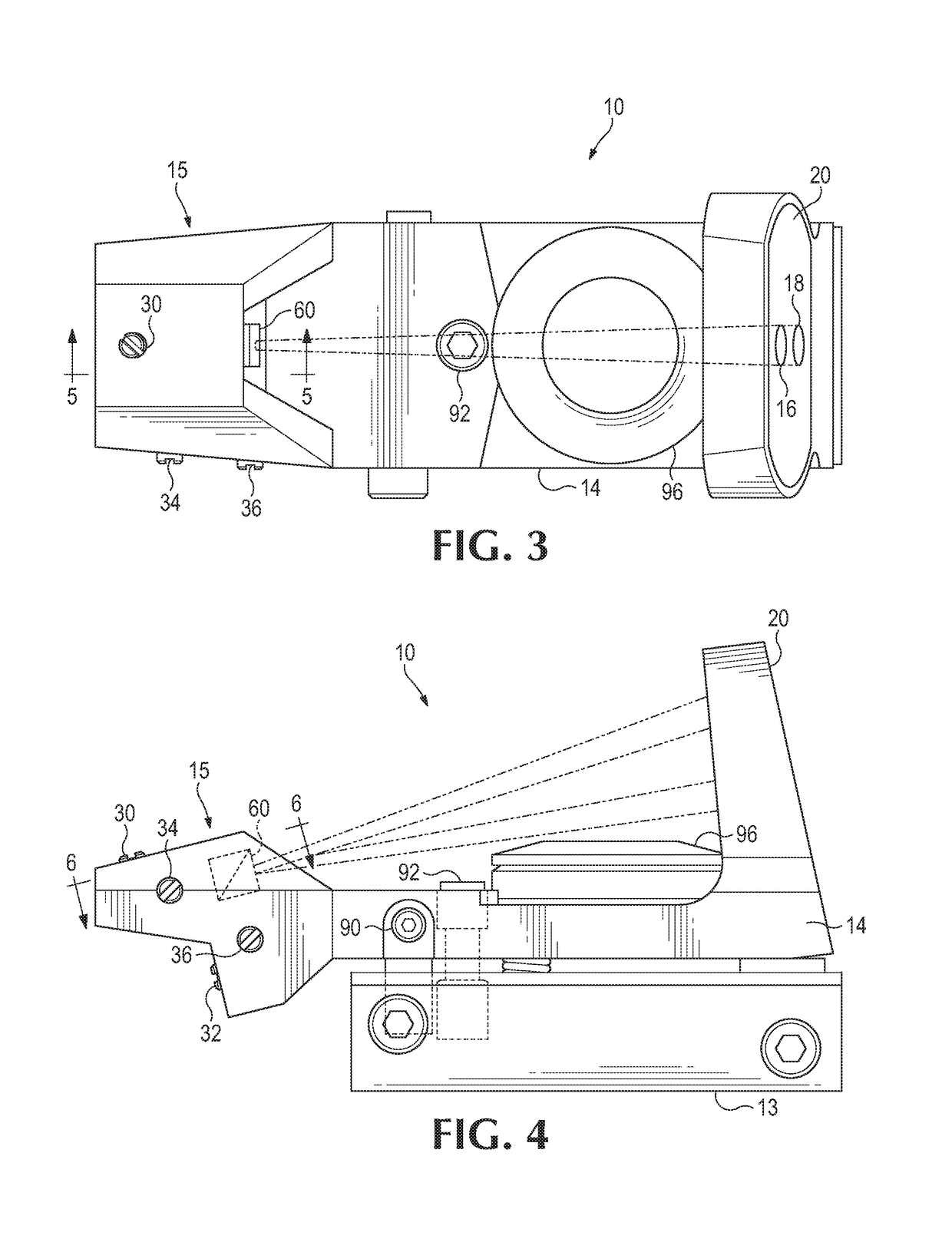
[0023]Referring now to FIGS. 3-6, a first reticle elevation adjustment actuator 30, and a second reticle elevation adjustment actuator 32 (FIG. 4), bot...


PUM


Abstract

A reflex sight, having a mounting base that has an engagement element for attachment to a firearm. Also, a collimating front lens is mounted on the mounting base. A first reticle projection system projects a first reticle onto the front lens, at a first position, the first position being user adjustable, relative to the mounting base, by a first actuation assembly. In addition, a second reticle projection system, projecting a second reticle onto the front lens at a second position, the second position being user adjustable, relative to the first position by a second actuation assembly.

Description

BACKGROUND[0001]Short range projectile weapons, for example pistols, shotguns and crossbows, typically have a lower barrel velocity than a rifle, resulting in significant variation in bullet drop, dependent on range, even at a relatively short range, for example 50 yards. The reflex sights typically used to aid a shooter in aiming such a firearm, however, only permit a single indicator of where a bullet will hit, thereby requiring a shooter to form a mental estimate of the hitting point for a range different from that for which the reticle position has been set.[0002]Also, there is a fair amount of uncertainty in the angle at which a projectile will leave the weapon, or for a shotgun, the area over which pellets will hit. There are currently limited options for assisting a shooter in forming an estimate of an area over which a projectile is likely to hit, or shotgun pellets will hit. Conversely, there are limited options for determining where a bullet will quite certainly not hit, s...

Claims


Application Information

Patent Timeline
IPC IPC(8): F41G1/30F41G3/08
CPCF41G3/08F41G1/30
Inventor THOMAS, MARKTHOMAS, MITCHELL
Owner GARMIN INT
Why Eureka
Eureka Blog
Learn More