
Ultrasonic tactile sensor for detecting clamping force

a tactile sensor and robotic arm technology, applied in the field of tactile sensors, can solve the problems of blind spots, complicated manufacturing process of these tactile sensors, and wrong judgment or determination of fetching made by the tactile sensor of the robotic arm, and achieve the effect of high cost and lack of sensitivity and resolution

Inactive Publication Date: 2019-03-26
SOUTHERN TAIWAN UNIVERSITY OF TECHNOLOGY
View PDF9 Cites 0 Cited by
  • Summary
  • Abstract
  • Description
  • Claims
  • Application Information

AI Technical Summary

Benefits of technology

[0006]In view of the drawbacks of the conventional sensors such as the complicated manufacturing process, high cost, and lacking of sensitivity and resolution, it is a primary objective of the present invention to use a spherical microstructure as a sensing element and an ultrasonic sensing to analyze the pressure exerted on the sensing element and feed back the shape, and such application is applied to a robotic arm for precision fetching and assembling while achieving the effect of ensuring the quality and safety management of the object.

Problems solved by technology

However, most of the industrial robotic arms primarily use vision for detection and are lack of a feedback mechanism for the tactile sensing, thus causing blind spots of the visual sensing and errors on determining distance easily, and resulting in a wrong judgment or determination of fetching made by the sensor of the robotic arm.
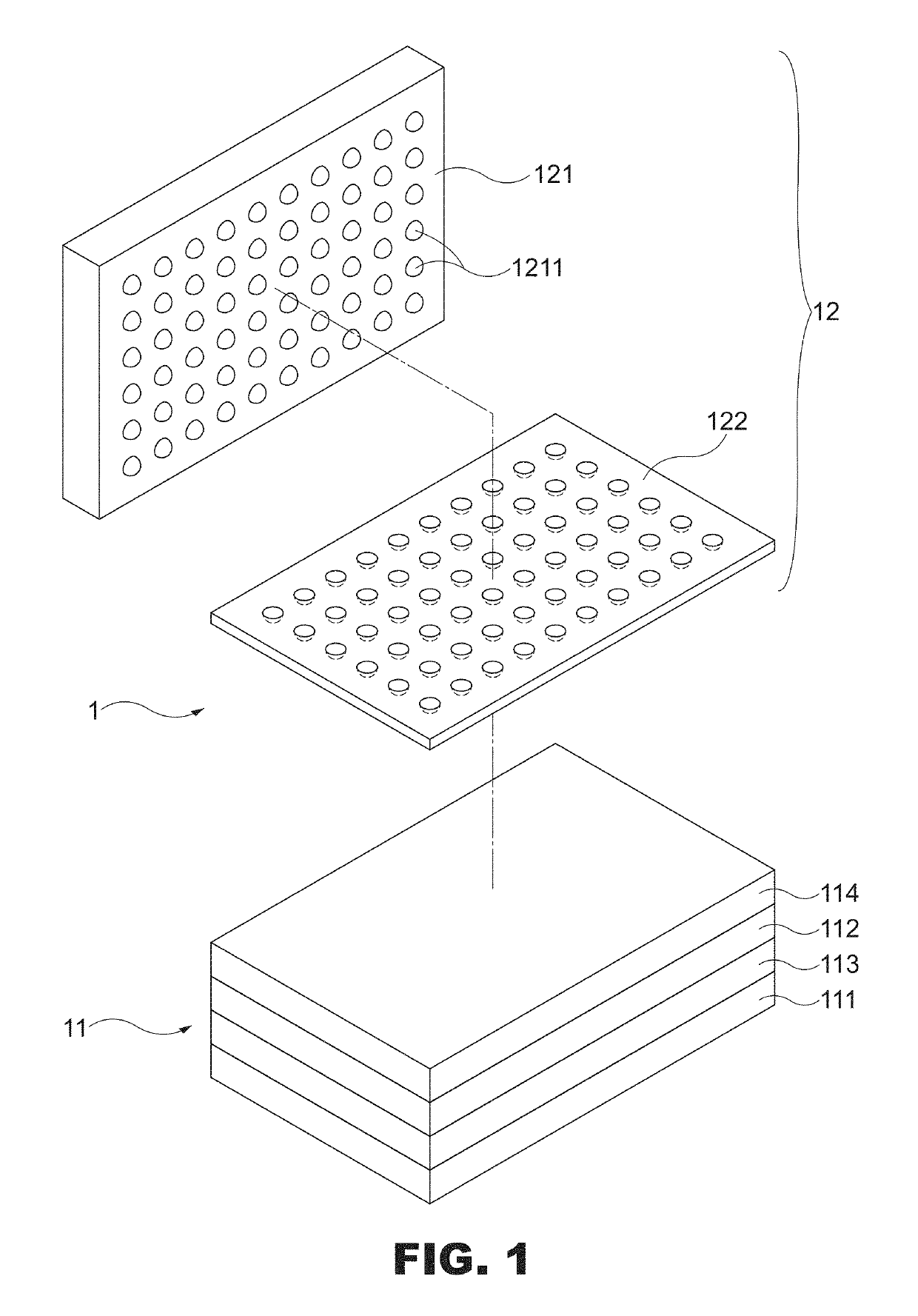
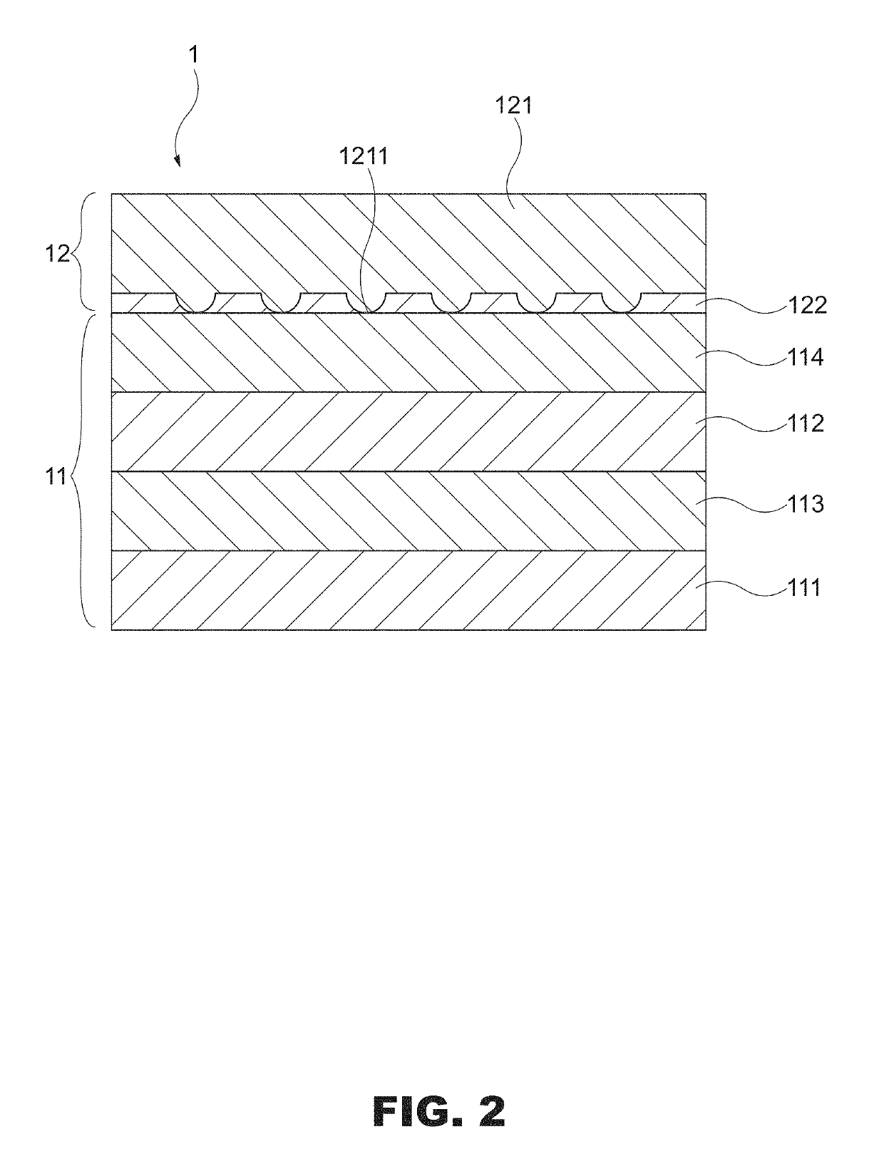
Although the conventional tactile sensors can detect a clamping force by different principles, the manufacturing process of these tactile sensors is more complicated.
In addition, the present thin sensor available in the market is unable to reflect the reading and lack of sensitivity and resolution.

Method used


Image

  • Ultrasonic tactile sensor for detecting clamping force
  • Ultrasonic tactile sensor for detecting clamping force
  • Ultrasonic tactile sensor for detecting clamping force

Examples


Embodiment Construction

[0015]The above and other objects, features and advantages of this disclosure will become apparent from the following detailed description taken with the accompanying drawings.

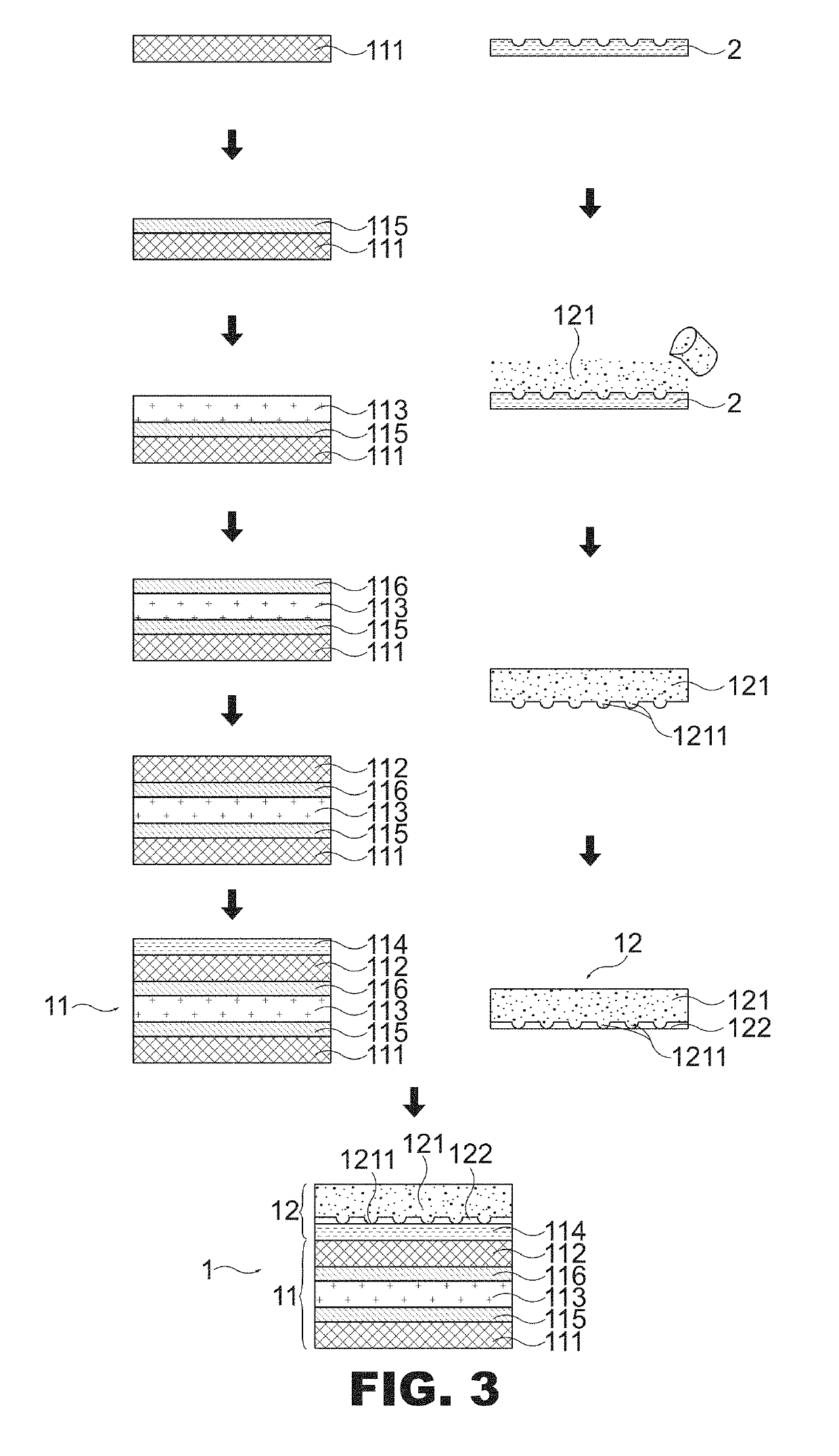
[0016]With reference to FIGS. 1 and 2 for an ultrasonic tactile sensor of the present invention, the ultrasonic tactile sensor 1 comprises an ultrasonic detector 11 and a sensing layer 12. Wherein, the ultrasonic detector 11 is provided for detecting the contact area of a first soft layer 121 of a sensing layer 12 to derive the force exerted on the tactile sensor 1, and the ultrasonic detector 11 further comprises a piezoelectric film emitting layer (Tx) 111, a piezoelectric film receiving layer (Rx) 112, a glass layer 113 and a packaging layer 114, wherein the piezoelectric film emitting layer 111 is provided for exciting ultrasonic shock waves, and the piezoelectric film emitting layer 111 is preferably made of polyvinylidene fluoride (PVDF); the piezoelectric film receiving layer (Rx) 112 is provided for se...


PUM

PropertyMeasurementUnit
frequencyaaaaaaaaaa
clamping forceaaaaaaaaaa
forceaaaaaaaaaa

Abstract

An ultrasonic tactile sensor for detecting a clamping force includes an ultrasonic detector and a sensing layer, and the sensing layer includes a first soft layer and a second soft layer, and the first soft layer has plural spherical microstructures arranged in contact with the ultrasonic detector, so that after a pressure is applied to the sensing layer, the ultrasonic detector generates an ultrasonic wave and receives a reflected wave signal, and the signal is provided for identifying the contact area of the spherical microstructures and deriving the force exerted on the tactile sensor.

Description

FIELD OF THE INVENTION[0001]The present invention relates to a tactile sensor, in particular to the tactile sensor for detecting a clamping force of robotic arms.BACKGROUND OF THE INVENTIONDescription of the Related Art[0002]According to the International Federation of Robotics, data show that robotic arms are used extensively in the field of industrial automation. Since the application of the robotic arms can reduce or eliminate unpredictable human errors that adversely affect the precision and durability of a product, therefore the demand for robotic arms in different industries becomes increasingly larger. However, most of the industrial robotic arms primarily use vision for detection and are lack of a feedback mechanism for the tactile sensing, thus causing blind spots of the visual sensing and errors on determining distance easily, and resulting in a wrong judgment or determination of fetching made by the sensor of the robotic arm.[0003]To overcome the aforementioned drawback, ...

Claims


Application Information

Patent Timeline
Patent Type & Authority Patents(United States)
IPC IPC(8): B25J13/08H01L41/193H01L41/25H01L41/053H01L41/113G01L1/16
CPCB25J13/084G01L1/165H01L41/25H01L41/1132H01L41/193H01L41/053G01L1/255G01L5/009H10N30/03H10N30/88H10N30/302H10N30/857
Inventor CHUANG, CHENG HSINCHEN, JIA WUN
Owner SOUTHERN TAIWAN UNIVERSITY OF TECHNOLOGY
Learn More