Drill attachment for tilling soil

a technology of attachment and soil, which is applied in the field of earth work, can solve the problems of not being able to mix fertilizer, requiring more storage space, and most powered tillers are more expensive, so as to achieve quick and efficient soil work, reduce labor intensity, and reduce labor intensity

Active Publication Date: 2019-04-16
KITTELSON RODNEY T
View PDF54 Cites 6 Cited by
  • Summary
  • Abstract
  • Description
  • Claims
  • Application Information

AI Technical Summary

Benefits of technology

[0018]Exemplary embodiments of the present invention solve inadequacies of the prior art by providing a drill shaft with a till plate, the combination that may be coupled with an ordinary hand drill or other rotary drive source. The drill shaft has a stabilizer tip that protrudes beyond the till plate. The till plate includes a plurality of teeth that are operative to dig into and work top soil, while a generally planar disk-shaped body member at the top of the till plate helps to break up soil and debris, and resists sinking below the surface of the soil. Optional weed-out and hole tools are also provided, to broaden the applications for the present invention.
[0020]A first object of the invention is to provide a powered tool that can quickly and efficiently work the soil and that requires minimal labor to operate. A second object of the invention is to provide such a tool that is economical to produce, requires minimal storage space, is suited to different terrains and surface areas, and will function well in diverse and difficult soils. Another object of the present invention is in at least one embodiment is to provide such a tool with intrinsic depth control that may loosen topsoil, remove weeds that could otherwise compete with desired plants, facilitate fertilizer application, and limit the soil being turned over to just topsoil, preserving deeper soil moisture. A further object of the invention in at least one embodiment is to provide a primary surface area of a cultivator head parallel to the surface of the ground, and as a result ensure that the head will not readily penetrate into the soil, while also through the design of the cultivator head simultaneously preventing or reducing the likelihood for accumulation of clumps of soil and other debris beneath the plate. Yet another object of the present invention in at least one embodiment is to provide cultivating tines throughout the depth plate, to thereby improve the working of all soil underneath and adjacent to the plate. An additional object of the invention in at least one embodiment is the provision of a stable tool relatively resistant to unsafe bouncing off of rocks and or other foreign obstacles. A further object of the invention is the provision of a tool fabricated from a unitary formed sheet metal cutting or cultivator head, substantially reducing the labor and difficulty of fabrication. Another object of the invention is to preserve metal during fabrication, thereby reducing the amount of waste or scrap resulting from production. An additional object of the invention is to form a cultivator head through a single stamping operation.

Problems solved by technology

Regardless, most powered tillers tend to be more costly, and also require more space for storage when not in use.
Furthermore, tillers are generally not desirable for mixing in fertilizer, due to difficulty to control the depth that the fertilizer may be mixed to.
Unfortunately, manual tools also require much more labor to operate.
Consequently, where there is a large area to be worked, or where there are many weeds to be removed, this approach can be unduly burdensome.
Also undesirably, in more difficult soils, such as clay, rocky, or heavy soils, these manual tools tend to be far less effective and require greater labor.
Most commonly, hand tools will only marginally penetrate and break up more difficult soils.
As a result, while surface soil and weed tops may be disturbed, the underlying soil and weed roots remain unaffected, allowing weeds to regrow quickly.
Consequently, a tool operator must exert significant force trying to control the depth of the tool.
In addition, when a rock or other foreign obstacle is encountered, the tool may jump or bounce relatively uncontrollably.
This can in some instances present a safety hazard, particularly where a relatively smaller or more frail individual is trying to operate the tool.
Furthermore, it is very desirable to efficiently break up the soil, and auger bits will tend to throw or displace chunks of soil, without breaking up the soil or adequately disrupting weed roots.
Further, these tools are generally significantly more expensive to produce, owing to the relatively large number of forming operations and welds required.
As may be apparent, this will require significant cost either in either labor required for handling and operations, or in the extreme equipment required to automate the inherently complex production.
Unfortunately, and as with the wire tools described herein above, these tools require substantial time, labor, and tooling for production and assembly of the many components.
The primary surface area of the cultivator head is parallel to the surface of the ground, and as a result the head will not readily penetrate into the soil.
However, and in spite of the easier fabrication and use, these tools have not gained widespread acceptance, and instead have been replaced by tools of other types described herein above.
One particularly vexing problem with these tools is the accumulation of clumps of soil and other debris that may collect beneath the plate.
This in turn defeats the intended depth control, and instead the tool rises off of the soil surface and becomes ineffective.
Another undesirable characteristic of these tools is the fact that the cutting or cultivating tines are formed solely around the perimeter of the depth plate, meaning that the operator must move the tool about somewhat blindly, since the plate blocks visibility of the underlying soil, with the hope and expectation that all of the soil will be adequately worked.
In addition, while De Conti uses the metal well, fabrication of the Bond et al cutting means wastes a significant amount of metal during a stamping operation.
Likewise, the Allen design wastes more metal from a stamping that is used in the tool, once again adding to the cost of fabrication.

Method used


Image

  • Drill attachment for tilling soil
  • Drill attachment for tilling soil
  • Drill attachment for tilling soil

Examples


Embodiment Construction

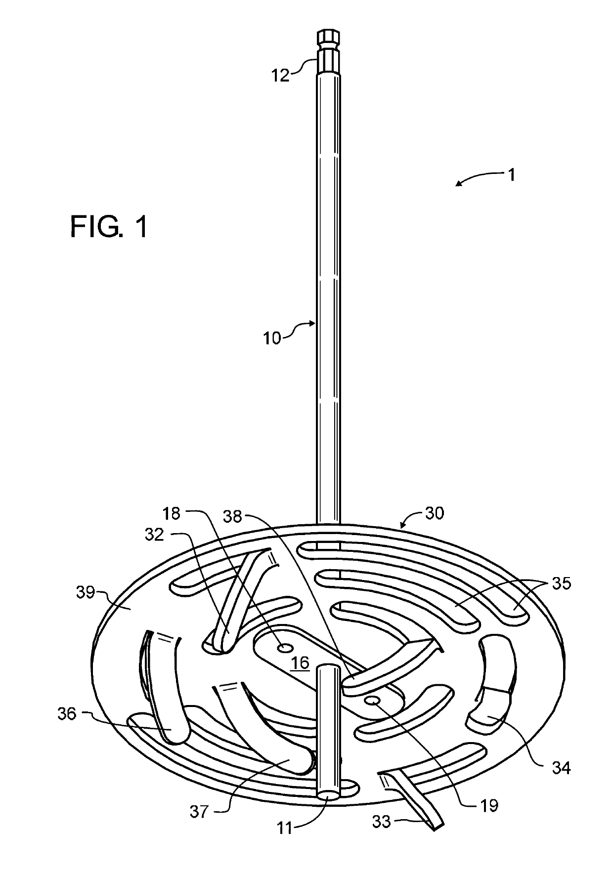
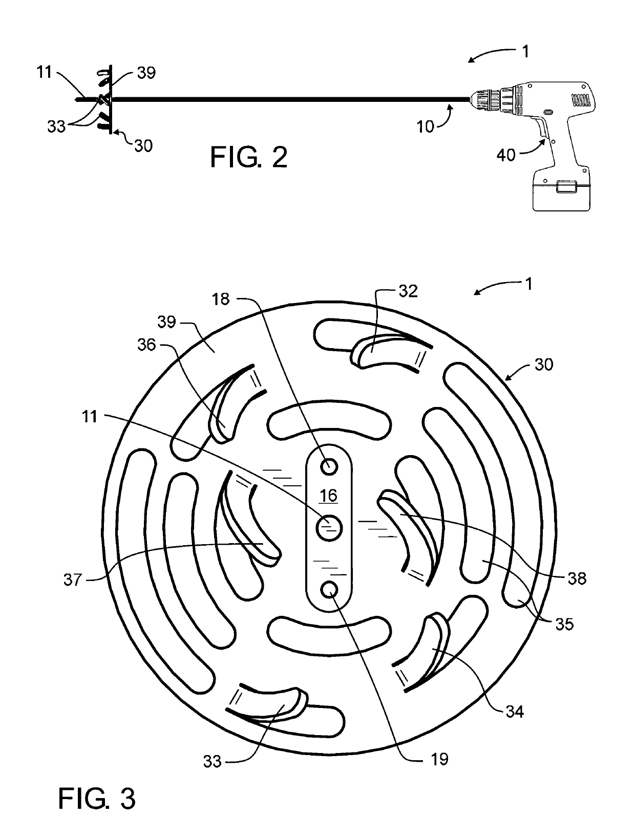
[0030]Manifested in the preferred embodiment, the present invention provides a drill attachment for tilling soil 1 that can quickly and efficiently work the soil and that requires minimal labor to operate. In a preferred embodiment of the invention illustrated in FIGS. 1 and 3, drill attachment for tilling soil 1 is comprised of a drill shaft 10 and a till plate 30. Drill shaft 10 preferably extends beyond till plate 30 to define a stabilizer tip 11, thereby resisting sudden transverse movements of drill attachment 1 when in use. In addition, stabilizer tip 11 serves as a pilot or guide, helping to accurately position till plate 30 when working in close spaces. The length of stabilizer tip 11 is not critical to present invention, and so will be varied by a designer in light of the teachings described herein. Nevertheless, for exemplary purposes only and not limiting the present invention solely thereto, stabilizer tip 11 may be several inches in length.

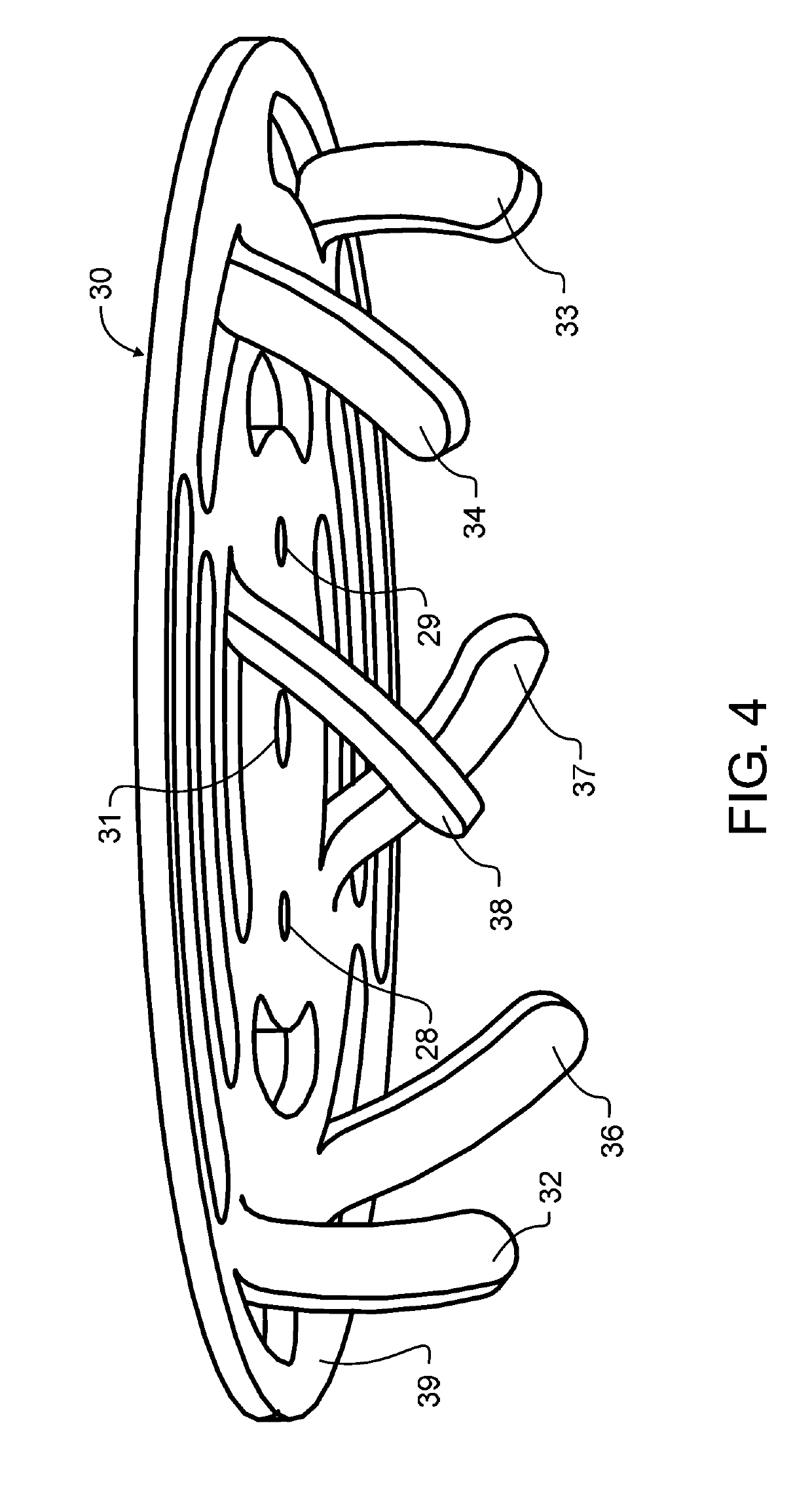
[0031]A plurality of teeth 32-...


PUM


Abstract

A drill attachment for tilling soil has an extended drill shaft that is coupled with a till plate. The combination may be driven by an ordinary hand drill. The drill shaft has a stabilizer tip that protrudes beyond the till plate. The till plate includes a plurality of teeth that dig into and work top soil, while a generally planar disk-shaped body member at the top of the till plate prevents the till plate from sinking below the surface of the soil. The teeth are stamped from the till plate, forming openings in the generally planar disk-shaped body member. These openings and other optional openings cooperate with the teeth to further break up clumps of soil, and help to balance forces from the teeth pulling into the soil against the force of the body member that resists sinking into the earth. Optional weed-out and hole tools are also disclosed.

Description

CROSS REFERENCE TO RELATED APPLICATIONS[0001]The present application claims the benefit of U.S. provisional patent application 62 / 262,549 filed Dec. 3, 2015 of like title and inventorship, the teachings and entire contents which are incorporated herein by reference.BACKGROUND OF THE INVENTION1. Field of the Invention[0002]The present invention relates generally to the field of earth working, and more particularly to tools rotary driven about a generally vertical axis. In one manifestation, the invention is a power drill tool including accessories operative to loosen soil, incorporate fertilizer into soil, and remove weeds therefrom.2. Description of the Related Art[0003]Prior to planting, the topsoil needs loosened. Subsequent to planting, loosening the topsoil between plants not only benefits the plants, but also removes weeds that could otherwise compete with the plants. In addition, both prior and subsequent to planting, it may be desirable to mix fertilizer into the soil. While ...

Claims


Application Information

Patent Timeline
Patent Type & Authority Patents(United States)
IPC IPC(8): A01B1/14A01B1/06A01B33/08A01B1/16A01B33/06
CPCA01B1/065A01B33/085A01B33/06
Inventor KITTELSON, RODNEY T.
Owner KITTELSON RODNEY T
Why Eureka
Try Eureka