
Reloadable sheath for catheter system for deploying vasoocclusive devices

a vasoocclusive device and reloadable technology, applied in the field of system and method for delivering intravascular interventional devices, can solve the problem that the available vasoocclusive devices are not reused during patient procedures, and achieve the effect of minimizing loss

Inactive Publication Date: 2019-04-16
DEPUY SYNTHES PROD INC
View PDF86 Cites 0 Cited by
  • Summary
  • Abstract
  • Description
  • Claims
  • Application Information

AI Technical Summary

Benefits of technology

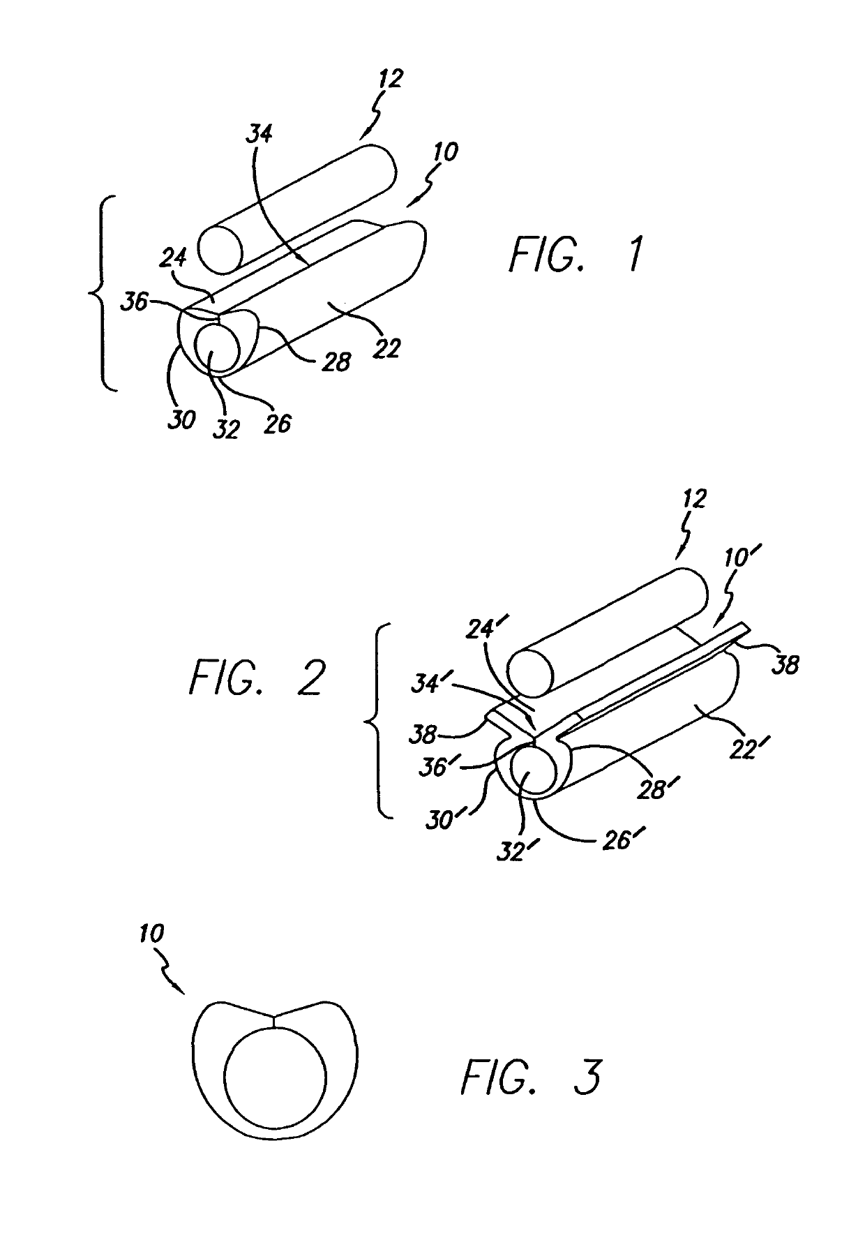
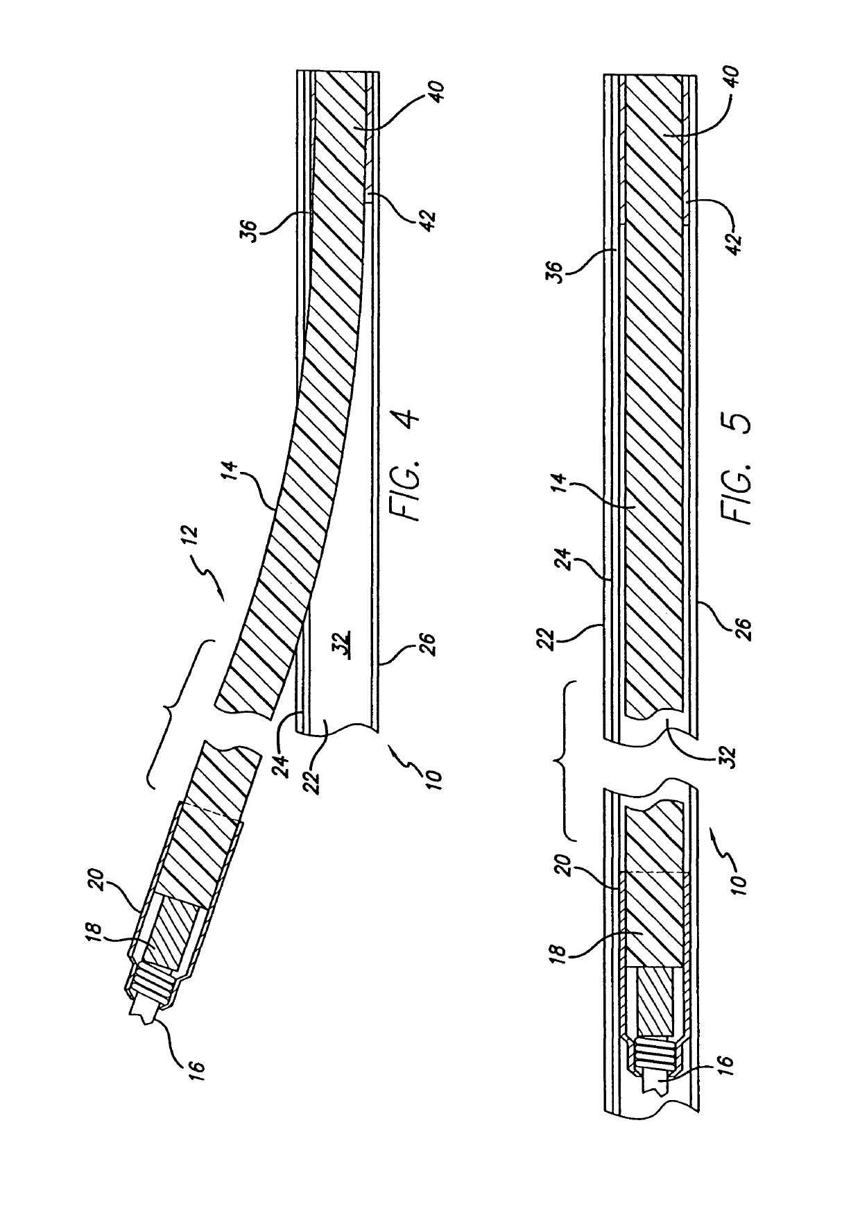
[0006]Briefly, and in general terms, the present invention provides for an introducer sheath for vasoocclusive devices that can be loaded onto a vasoocclusive embolic coil assembly after removal of the vasoocclusive embolic coil assembly from a microcatheter, to permit reuse of the vasoocclusive embolic coil assembly during a clinical procedure and to minimize the loss of an otherwise acceptable vasoocclusive embolic coil product.
[0009]In one embodiment, the sheath may further include wing members extending outwardly from the angled configuration on the outside surface of the hollow, elongated tubular member to facilitate insertion of the vasoocclusive device into the sheath. The wing members of the angled configuration on the outside surface of the hollow, elongated tubular member have opposing exterior surfaces typically forming an interior angle of about 110° to 150°. In a variation of these embodiments, the sheath may be formed in combination with the vasoocclusive device, the elongated tubular member consisting of a length with no slot attached to a segment of the flexible pusher member to facilitate initiation of loading of the flexible pusher member and embolic coil into the sheath.

Problems solved by technology

Some available vasoocclusive devices are not reused during a patient procedure if they are removed during the procedure, due to the inability to reload the device into the microcatheter.

Method used


Image

  • Reloadable sheath for catheter system for deploying vasoocclusive devices
  • Reloadable sheath for catheter system for deploying vasoocclusive devices

Examples


Embodiment Construction

[0016]A reloadable sheath 10 for a therapeutic vasoocclusive device 12. The vasoocclusive device typically includes an assembly of a flexible pusher member 14 and an embolic coil 16 (only a portion of which is shown) attached to the flexible pusher member, as illustrated in FIGS. 4 and 5. The flexible pusher member may, for example, include an elongated optical fiber having a distal end 18 sheathed in a tubular collar 20 of shape memory material for retaining the embolic coil on the distal end of the flexible pusher member. The optical fiber can be sized to be quite flexible and bend sufficiently to follow the body lumen. Alternatively, the elongated pusher can be formed of suitable materials for conducting energy, such as radio frequency energy, magnetic energy, electrical energy, or ultrasonic energy, such as an elongated metal member, for example, or of a heat pipe for conducting heat from a heat source. Alternatively, the flexible pusher can consist of a tubular or solid wire co...


PUM


Abstract

The introducer sheath can be loaded onto a vasoocclusive device after removal of the vasoocclusive device from a microcatheter, to permit the vasoocclusive embolic coil assembly to be used again during a clinical procedure. The sheath includes a hollow, elongated tubular member with a longitudinal slot formed in the upper wall of the elongated tubular member and extending along the length of elongated tubular member. The upper wall of the elongated tubular member adjacent to the slot has an angled configuration to accept the vasoocclusive device. The sheath may include wing members extending outwardly from the angled configuration on the outside surface of the hollow, elongated tubular member to facilitate insertion of the vasoocclusive device into the sheath. The elongated tubular member may also consist of a segment with no slot attached to a flexible pusher member to facilitate initiation of loading of the vasoocclusive device into the sheath.

Description

RELATED APPLICATIONS[0001]This is a continuation of application Ser. No. 10 / 802,520, filed 16 Mar. 2004 now abandoned, which is a division of application Ser. No. 09 / 990,759, filed 9 Nov. 2001, now U.S. Pat. No. 6,716,223.BACKGROUND OF THE INVENTION[0002]This invention relates generally to devices for interventional therapeutic treatment or vascular surgery for treatment of defects in the vasculature, and more particularly concerns a system and method for delivering intravascular interventional devices, such as for treatment of aneurysms.[0003]Vascular interventional devices such as vasoocclusive devices are typically placed within the vasculature of the human body by use of a catheter. Vascular interventional devices such as stents can be placed within an occluded vessel to facilitate blood flow through the vessel, and vasoocclusive devices are typically either placed within a blood vessel to block the flow of blood through a vessel making up that portion of the vasculature through...

Claims


Application Information

Patent Timeline
Patent Type & Authority Patents(United States)
IPC IPC(8): A61M29/00A61B17/12A61M25/06
CPCA61B17/12022A61B17/1214A61M25/0662A61M25/0668A61B2017/12054A61B2017/12072A61B2017/12077A61B2017/1205
Inventor LEOPOLD, ERICMCEVERS, BRUCE
Owner DEPUY SYNTHES PROD INC
Learn More