Noise reduction members for motor vehicle fenders

a technology for motor vehicles and fenders, applied in the direction of transportation and packaging, synthetic resin layered products, chemistry apparatuses and processes, etc., can solve the problems of no less easily the noise entering the front fender inner space is easy to reach the vehicle cabin, and the noise entering the rear fender inner space is easy to enter. , to achieve the effect of reducing deformation and high sound insulation and sound absorption performan

Active Publication Date: 2019-04-16
NISHIKAWA RUBBER
View PDF13 Cites 2 Cited by
  • Summary
  • Abstract
  • Description
  • Claims
  • Application Information

AI Technical Summary

Benefits of technology

[0013]Furthermore, the seal member disclosed in Japanese Unexamined Patent Publication No. 2010-115985 includes a substrate and a pair of sponge plates sandwiching the substrate on both sides, thus complicating the manufacturing process. In addition, just like Japanese Utility Model Publication No. 3048125 and Japanese Unexamined Patent Publication No. 2004-26060, the final form of the product is a simple single flat plate, of which the sound absorption effect would not be so high.
[0045]According to the eighth aspect of the present disclosure, the hard plate member significantly reduces the deformation of the first and second wall portions, thus allowing the first and second wall portions to maintain high sound insulation and sound absorption performances for a long time.

Problems solved by technology

Furthermore, the rear end of the front fender inner spaces is only separated from the vehicle cabin via a panel, for example, and therefore, the noise entering the front fender inner spaces reaches the vehicle cabin easily.
Likewise, the noise entering the rear fender inner spaces will no less easily enter the vehicle cabin located in front of the rear fender inner spaces.
Thus, there is a concern about the noise that has entered a fender inner space from the front reaching a rear region of the fender inner space and eventually entering the vehicle cabin through an entrance without being reduced.
However, the cushion member, having a simple flat plate shape, would certainly achieve some sound insulation effect but would not achieve so high a sound absorption effect.
Furthermore, the seal member disclosed in Japanese Unexamined Patent Publication No. 2010-115985 includes a substrate and a pair of sponge plates sandwiching the substrate on both sides, thus complicating the manufacturing process.

Method used


Image

  • Noise reduction members for motor vehicle fenders
  • Noise reduction members for motor vehicle fenders
  • Noise reduction members for motor vehicle fenders

Examples


first embodiment

[0064](First Embodiment)

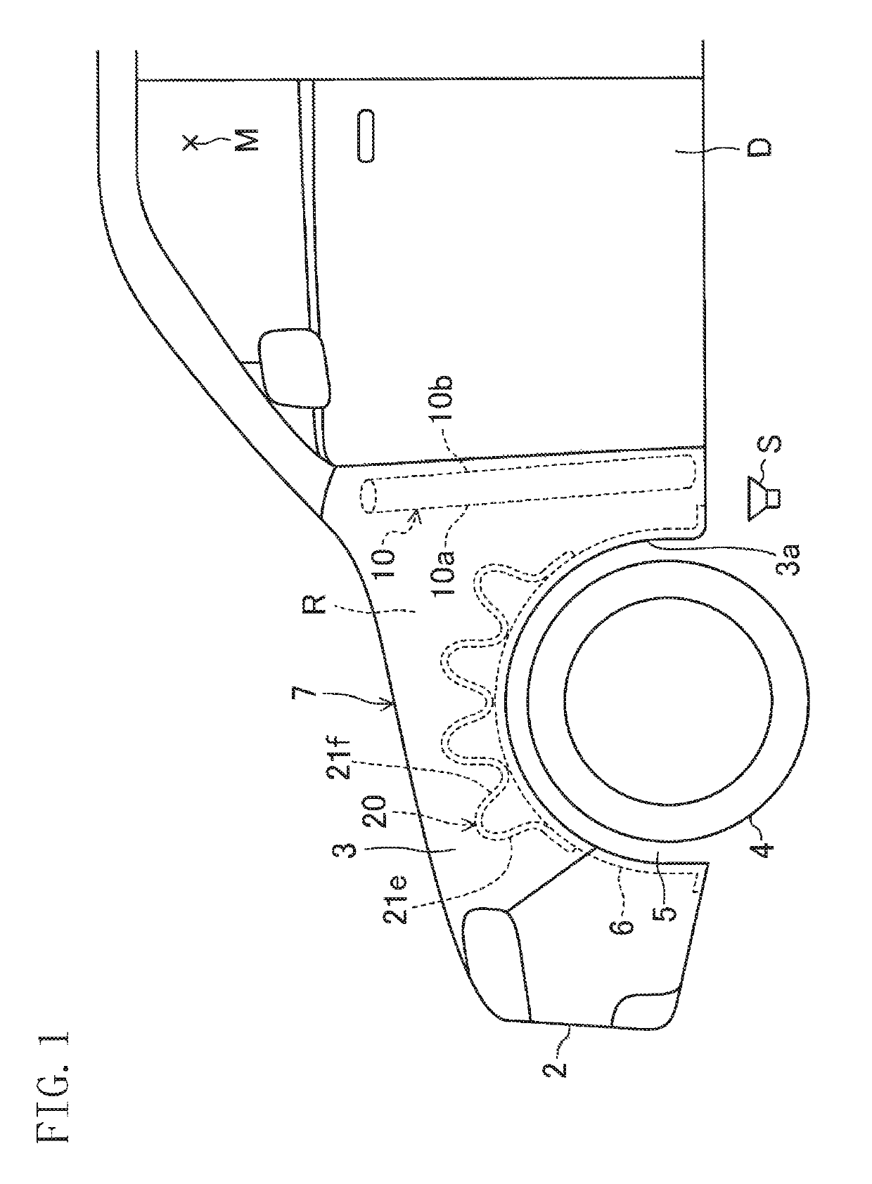
[0065]FIG. 1 is a front left side view of a motor vehicle 1 including a front-fender noise reduction member 20 according to a first embodiment of the present disclosure. In the following description of embodiments, the front side of the motor vehicle will be hereinafter simply referred to as “front,” the rear side thereof “rear,” the left side thereof “left,” and the right side thereof “right,” respectively.

[0066](Configuration of Motor Vehicle's Front)

[0067]The motor vehicle 1 is a so-called “passenger car” and is provided with an engine compartment (not shown) equipped with an engine and other parts in the front. Behind that engine compartment, there is a vehicle cabin to seat an occupant and passengers. The engine compartment and the vehicle cabin are separated from each other by a dash panel. The motor vehicle 1 is provided with a front bumper 2 at the frontend thereof. The front bumper 2 has an opening for letting cooling air into the engine compartment....

second embodiment

[0100](Second Embodiment)

[0101]FIGS. 9-11 illustrate a second embodiment of the present disclosure. The second embodiment is the same as the first embodiment described above except the structure of the front-fender noise reduction member. Thus, any member of the second embodiment having substantially the same function as its counterpart of the first embodiment described above will be designated by the same reference numeral as the counterpart's and will not be described all over again to avoid redundancies. Instead, the following description of the second embodiment will be focused on only the differences from the first embodiment.

[0102]Specifically, a front-fender noise reduction member 30 according to the second embodiment is fixed to the upper surface of the curved plate portion 6a of an associated inner fender 6, has a cylindrical shape upwardly protruding from the upper surface, and has its top end closed with a closing portion 30a. The front-fender noise reduction member 30, h...

third embodiment

[0107](Third Embodiment)

[0108]FIG. 12 illustrates a third embodiment of the present disclosure. The third embodiment is the same as the first embodiment described above except that the third embodiment does not include the rear noise reduction member 10. Thus, any member of the third embodiment having substantially the same function as its counterpart of the first embodiment described above will be designated by the same reference numeral as the counterpart's and will not be described all over again to avoid redundancies. This third embodiment, also including the front-fender noise reduction members 20, can also achieve the same advantages as the first embodiment described above.


PUM

PropertyMeasurementUnit
thicknessaaaaaaaaaa
frequencyaaaaaaaaaa
frequencyaaaaaaaaaa

Abstract

Disclosed herein is a technique for further improving the quietness in a vehicle cabin while reducing an increase in the weight of a motor vehicle. A noise reduction member, arranged in a fender inner space defined between a fender panel serving as an exterior panel for a motor vehicle and an inner fender forming a wheelhouse, includes a pair of wall portions which are made of a foamed material and arranged to be spaced apart from each other.

Description

CROSS-REFERENCE TO RELATED APPLICATION[0001]This application claims priority to Japanese Patent Application No. 2016-133352 filed on Jul. 5, 2016 and Japanese Patent Application No. 2017-100116 filed on May 19, 2017, the entire disclosures of which are hereby incorporated by reference.BACKGROUND ART[0002]The present disclosure relates to noise reduction members for motor vehicle fenders, and more particularly relates to the field of technology of a structure for reducing the noise entering a vehicle cabin.[0003]In general, each fender of a motor vehicle includes a fender panel serving as an exterior panel for the motor vehicle and an inner fender forming a wheelhouse. A fender inner space is defined between the fender panel and the inner fender. Note that a motor vehicle includes a plurality of fenders. One pair of fenders arranged closer to its front wheels is called “front fenders,” while another pair of fenders arranged closer to its rear wheels “rear fenders.” When it is not nec...

Claims


Application Information

Patent Timeline
Patent Type & Authority Patents(United States)
IPC IPC(8): B62D33/00B60R13/08B32B5/18B32B3/28B32B27/08
CPCB60R13/0815B32B3/28B32B27/08B60R13/0861B32B5/18B32B2307/102B32B27/065B32B27/322B32B27/36B32B2250/03B32B2250/40B32B2266/0207B32B2266/0228B32B2266/025B32B2605/00
Inventor ONISHI, NOBUKAZUKOHARA, YOSHIHIRO
Owner NISHIKAWA RUBBER
Why Eureka
Try Eureka