
Modular solar power generation apparatus

a solar power generation and module technology, applied in electrical devices, photovoltaics, photovoltaic monitoring, etc., can solve the problems of insufficient electric energy produced by single solar cell, easy failure to meet the needs of installation and maintenance, and weaken the power generation efficiency of solar panels, etc., to achieve easy installation and maintenance, less susceptible to damage, and upward broaden the effect of width

Inactive Publication Date: 2019-04-16
BEE SPACE CO LTD
View PDF5 Cites 0 Cited by
  • Summary
  • Abstract
  • Description
  • Claims
  • Application Information

AI Technical Summary

Benefits of technology

The present invention is a modular solar power generation apparatus that features solar panels with upward broadened widths, allowing for easy installation and maintenance. The apparatus also includes a light guiding unit, connection units, and a shield to protect the solar panels from external collisions. Additionally, a frame may be added to further protect the solar panels from damages. The technical effects of the invention include convenient installation and maintenance of solar panels, multi-purpose applications, and efficient detection of damaged solar panels.

Problems solved by technology

However, a whole solar panel on which contiguous solar cells are integrated with one another for production of electric energy as required must be replaced completely for resurrection of the original power generating efficiency when a single solar cell on the solar panel fails and weakens power generating efficiency of a solar panel.
However, the “solar power light concentrator module” on which a single solar cell is mounted produces insufficient electric energy.
For production of electric energy as required, solar power assemblies should be installed on a large-scale flat area which is no easy feat for development and promotion of solar power generation.
However, some problems in the “spatial solar light concentrating device” and the “solar energy collector”, each of which are installed and maintained inconveniently, still remain to be solved, for example, some gaps exist between solar panels assembled at an angle of inclination result in loss of some light sources.

Method used


Image

  • Modular solar power generation apparatus
  • Modular solar power generation apparatus
  • Modular solar power generation apparatus

Examples


Embodiment Construction

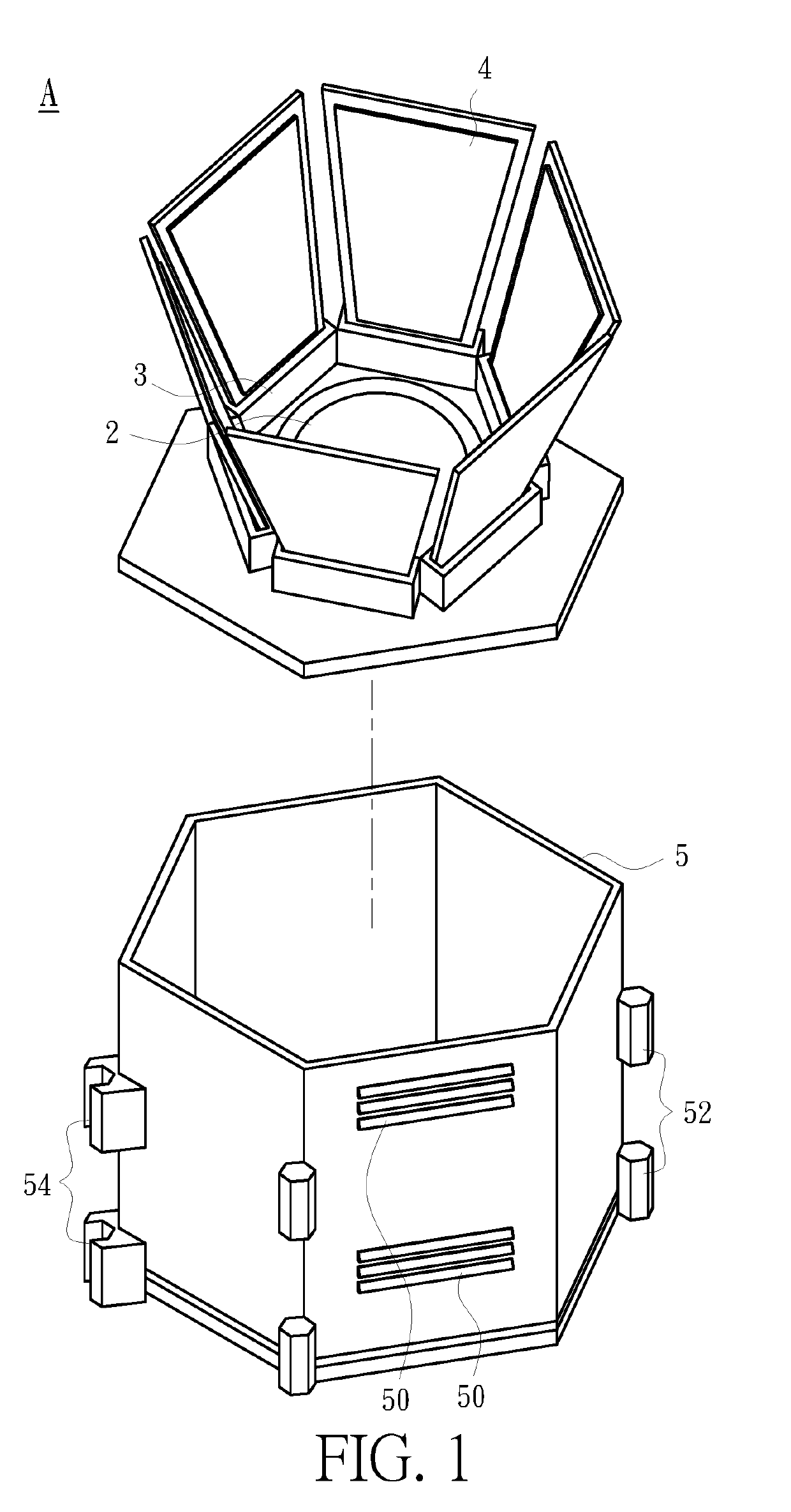
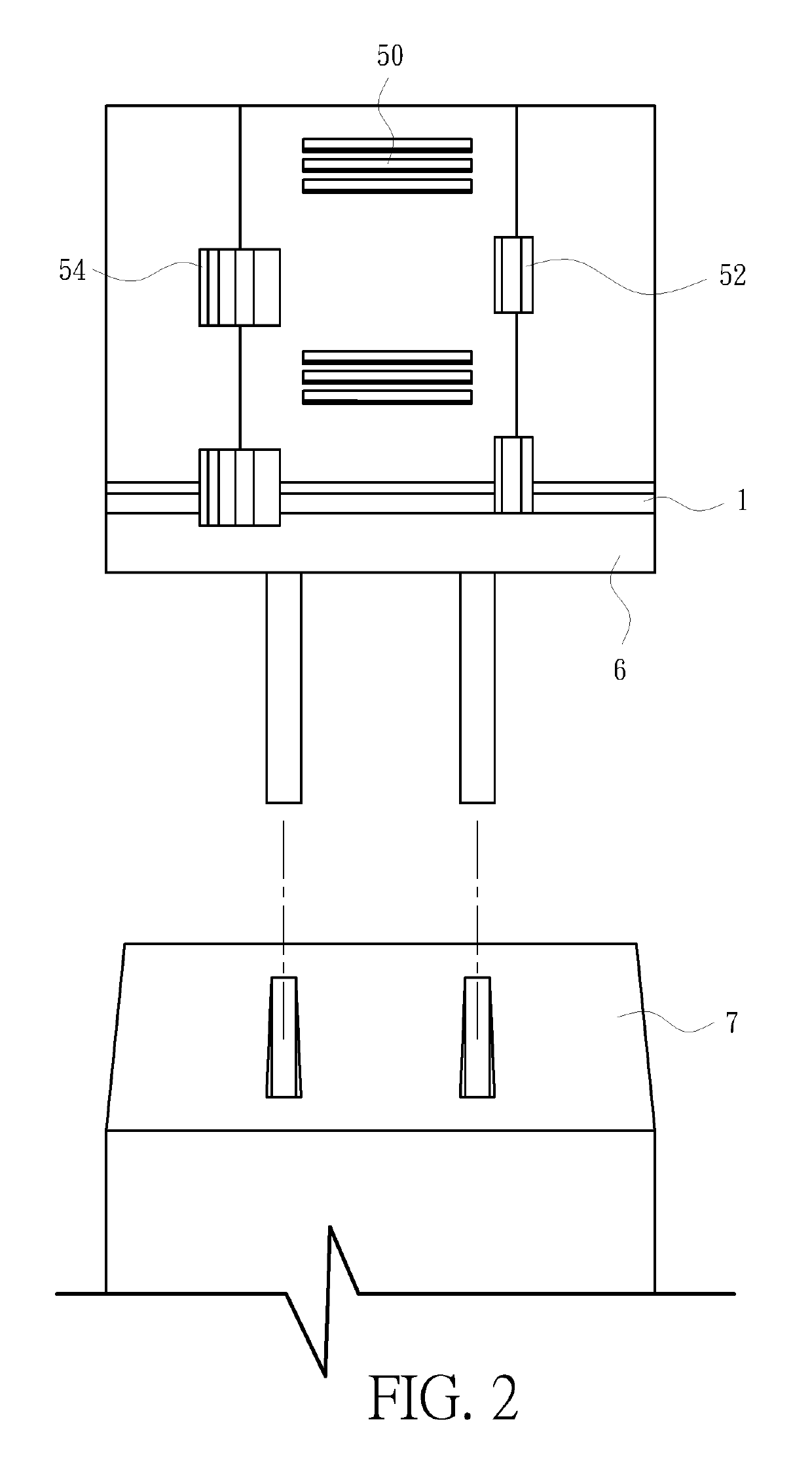
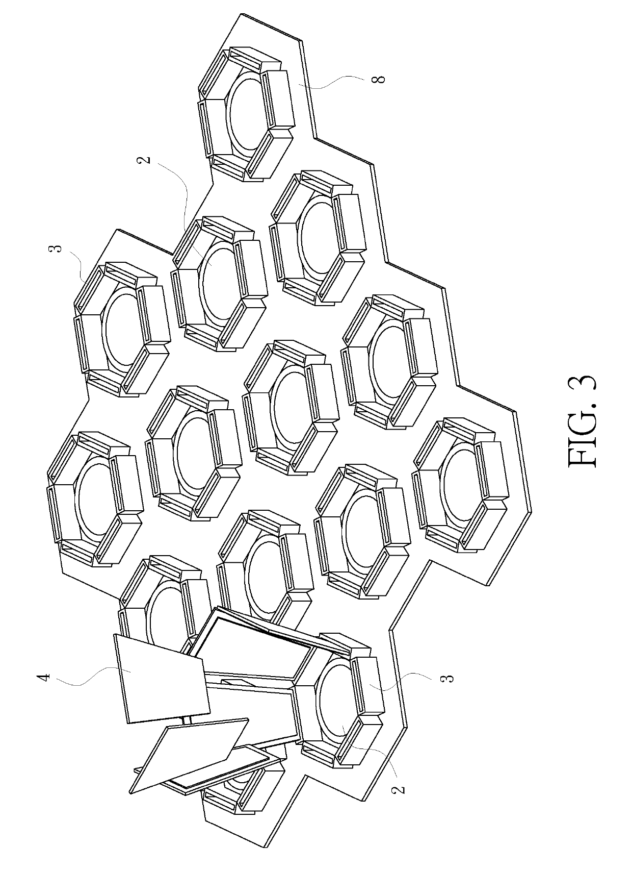
[0024]Referring to FIG. 1, which illustrates a modular solar power generation apparatus comprises a base plate 1, a light guiding unit 2, a plurality of connection units 3 and a plurality of solar panels 4; in a modular solar power generation apparatus, the light guiding unit 2, which is installed on the base plate 1, is a conical reflecting mirror or a circular-arc reflecting mirror or prism for adequate guidance of extraneous light rays along a preset path according to light refraction and reflection principles. All connection units 3 circlewise mounted on the base plate 1 and encircling the light guiding unit 2 can be contiguous gold finger printed circuit board (PCB) sockets.

[0025]Furthermore, each the solar panel 4 is connected to one of the connection units 3 and comprises a gold finger PCB which is plugged into the connection unit 3 for transmission of generated electric energy to the connection unit 3 and the base plate 1 sequentially from which the electric energy is transm...


PUM


Abstract

The present disclosure relates to a modular solar power generation apparatus comprising a base plate, a light guiding unit, a plurality of connection units and a plurality of solar panels wherein: the light guiding unit is installed on the base plate; all connection units are circlewise mounted on the base plate and encircling the light guiding unit; each the solar panel, which is connected to one of the connection units, and the base plate form an angle of inclination by which each the solar panel features upward broadened widths such that any two neighboring solar panels allow their corresponding edges to be adjacent to each other and a gap in between to be narrowed for development of solar panels easily installed and maintained.

Description

[0001]The present application is based on PCT application number PCT / CN2015 / 096966, filed on Dec. 10, 2015, the disclosure of which is hereby incorporated by reference herein in its entirety.BACKGROUND OF THE INVENTION1. Field of the Invention[0002]The present disclosure relates to a solar power generation apparatus, particularly a solar power generation apparatus which adjusts an incident angle of light and reflects light within the incident angle adjusted.2. Description of the Prior Art[0003]As an environment-friendly renewable energy generation method, solar power generation which features no production of greenhouse gases such as carbon dioxide does not pollute environment during power generation.[0004]Moreover, a traditional solar panel is characteristic of a plurality of solar cells mounted on a sheet of base plate on which light rays (for example, sunlight) are projected for generation of electric energy from solar cells. However, a whole solar panel on which contiguous solar...

Claims


Application Information

Patent Timeline
Patent Type & Authority Patents(United States)
IPC IPC(8): H02S40/22H02S30/10H02S30/00H02S40/36H02S50/00H02S40/42
CPCH02S40/22H02S30/00H02S30/10H02S40/425H02S50/00H02S40/36Y02E10/52
Inventor HSU, YI-WENLIU, PO-CHUNGKUO, CHAN-YU
Owner BEE SPACE CO LTD
Learn More