Engine-driven generator

a technology of engine-driven generators and generators, which is applied in the direction of machines/engines, engine cooling apparatus, and feed systems, etc., can solve the problems of reducing the size of engine-driven generators, and achieve the effect of efficiently blowing

Active Publication Date: 2019-04-30
HONDA MOTOR CO LTD
View PDF39 Cites 13 Cited by
  • Summary
  • Abstract
  • Description
  • Claims
  • Application Information

AI Technical Summary

Benefits of technology

[0006]With this arrangement, the cylinder of the engine is disposed substantially vertically, and the fuel tank is disposed on that side of the cooling fan which is opposite to the generator unit. The fuel tank is vertically elongated to face the cylinder of the engine. The thus configured fuel tank is able to secure a large capacity. The fuel tank needs not to be disposed above the engine and, hence, a height dimension of the engine-driven generator can be reduced.
[0007]By virtue of the vertically disposed cylinder of the engine, a space is provided on a lateral side of the cylinder. The space is used for installation of the inverter, and the inverter is disposed beside the lateral side part of the air guide space. Furthermore, by virtue of the air shroud disposed between the inverter and the air guide space, the inverter can be cooled by the cooling fan. Cooling of the inverter by the cooling fan can thus be secured.
[0008]The inverter needs not to be disposed in front of the cooling fan and, hence, a length dimension of the engine-driven generator can be reduced. By virtue of a combination of the fuel tank disposed on a side of the cooling fan opposite to the generator unit, and the inverter disposed beside the lateral side part of the air guide space, downsizing of the engine-driven generator can be achieved.
[0010]Additionally, the air guide space for guiding air into the cooling fan is formed by and between the fuel tank and the cooling fan. Since the fuel tank is used to form the air guide space, this arrangement is able to obviate the need for a separate member used exclusively for forming the air guide space, and an increase in cost of the engine-driven generator can be suppressed.
[0012]By virtue of the guide protrusion formed on the rear wall of the fuel tank for guiding air from the air guide space to the entire area of the front side of the cooling fan, the air introduced in the air guide space can eventually be blown efficiently from the cooling fan as a cooling air. As a consequence, a sufficient amount of air can be introduced into the inverter and the inverter can be properly cooled by the thus introduced air. The generator unit and the engine can be more properly cooled by the cooling air blown from the cooling fan.

Problems solved by technology

With this arrangement, a size or dimension of the engine-driven generator in a direction along the crankshaft is relatively large, which will hinder down-sizing of the engine-driven generator.

Method used


Image

  • Engine-driven generator
  • Engine-driven generator
  • Engine-driven generator

Examples


Embodiment Construction

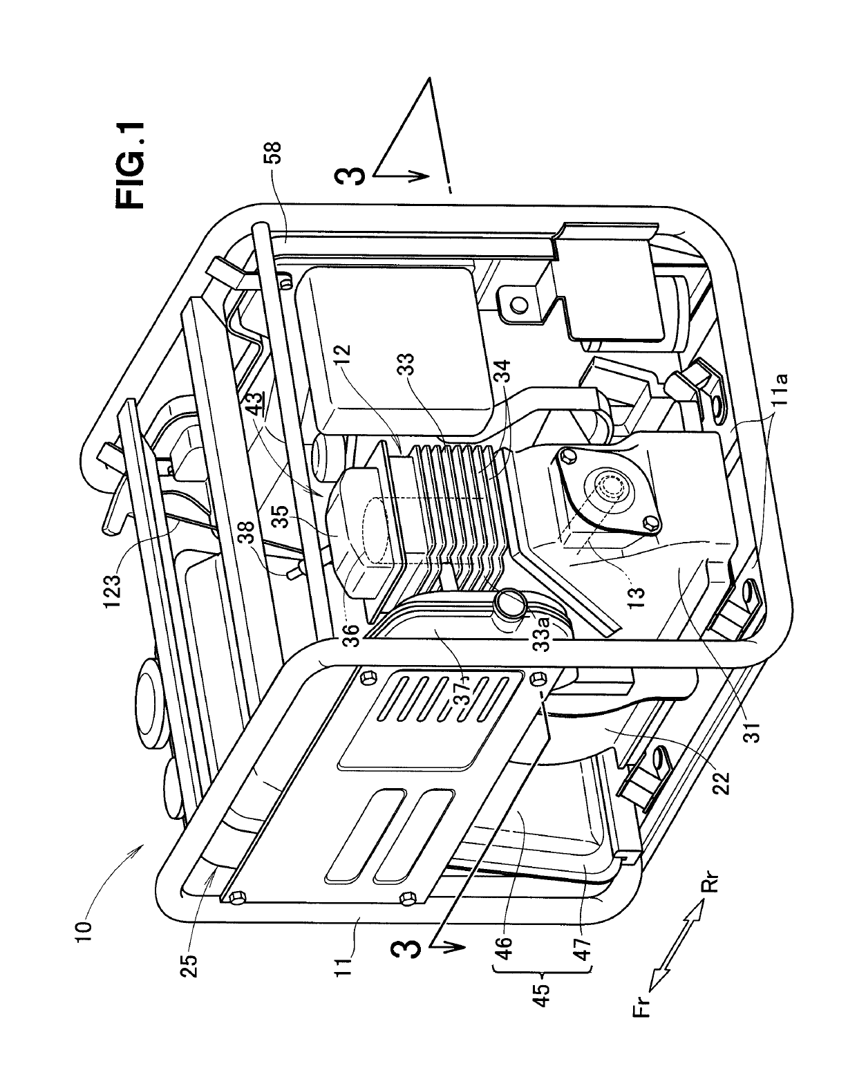
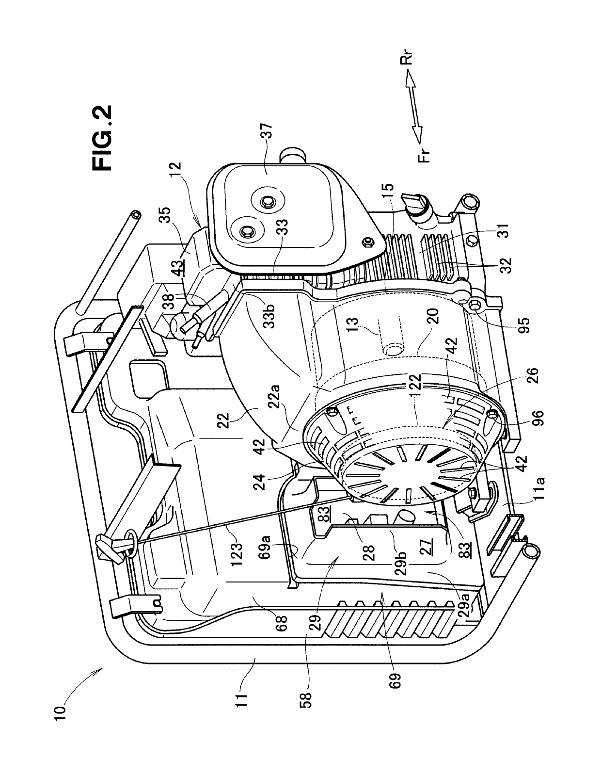
[0021]A certain preferred structural embodiment of the present invention will be described in greater details below, by way of example only, with reference to the accompanying sheets of drawings. In the drawings, “Fr” and “Rr” are used to refer to a front side or recoil cover side, and a rear side or engine side, respectively.

[0022]As shown in FIGS. 1 and 2, an engine-driven generator 10 embodying the present invention includes a vertical engine 12 mounted on a bottom 11a of a frame 11, a generator unit 15 provided in front of the engine 12, a cooling fan 20 provided in front of the generator unit 15, a fan cover 22 covering the cooling fan 20 and the generator unit 15, a recoil cover 24 attached to the fan cover 22, and a recoil starter 26 attached to the recoil cover 24.

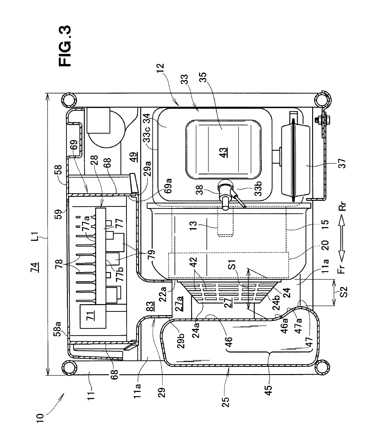
[0023]As shown in FIG. 3, the engine-driven generator 10 further includes a fuel tank 25 provided in front of the recoil cover 24, an air guide space 27 defined between the fuel tank 25 and the recoil cover 24, an ...


PUM


Abstract

An engine-driven generator includes a fuel tank disposed in front of a cooling fan, an air guide space defined between the fuel tank and the cooling fan, an inverter disposed beside a lateral side part of the air guide space, and an air shroud provided between the inverter and the air guide space. The fuel tank is vertically elongated to face a cylinder block of a vertical engine. A storage space having the inverter disposed therein is connected to the air guide space via the air shroud.

Description

FIELD OF THE INVENTION[0001]The present invention relates to an engine-driven generator configured to drive a generator unit by an engine and convert direct-current (DC) electric power generated by the generator unit into alternating-current (AC) electric power via an inverter.BACKGROUND OF THE INVENTION[0002]Some known engine-driven generators include a generator unit provided on one side of an engine in direct coupling with a crankshaft of the engine, and a fuel tank disposed on an opposite side of the engine. A typical example of such known engine-driven generators is disclosed in Japanese Patent Laid-open Publication (JP-A) No. 59-15633. The engine-driven generators are generally equipped with an inverter by means of which direct-current (DC) electric power generated by the generator unit is converted into alternating-current (AC) electric power. Furthermore, the engine-driven generators include a cooling fan provided coaxially with the engine crankshaft for cooling the inverter...

Claims


Application Information

Patent Timeline
Patent Type & Authority Patents(United States)
IPC IPC(8): F01P1/06F02B63/04F01P5/06
CPCF01P1/06F02B63/048F02B63/044F01P5/06F01P5/04F02B63/042F02M37/0076
Inventor TAKAHASHI, YUKIKASE, TAKUOSHIMOZONO, KAZUKIYANAI, KIYOMI
Owner HONDA MOTOR CO LTD
Why Eureka
Try Eureka