
Vane pump

a technology of a valve body and a valve body, which is applied in the direction of rotary/oscillating piston pump components, machines/engines, liquid fuel engines, etc., can solve problems such as unfavorable flow conditions

Active Publication Date: 2019-04-30
ZF FRIEDRICHSHAFEN AG
View PDF10 Cites 0 Cited by
  • Summary
  • Abstract
  • Description
  • Claims
  • Application Information

AI Technical Summary

Benefits of technology

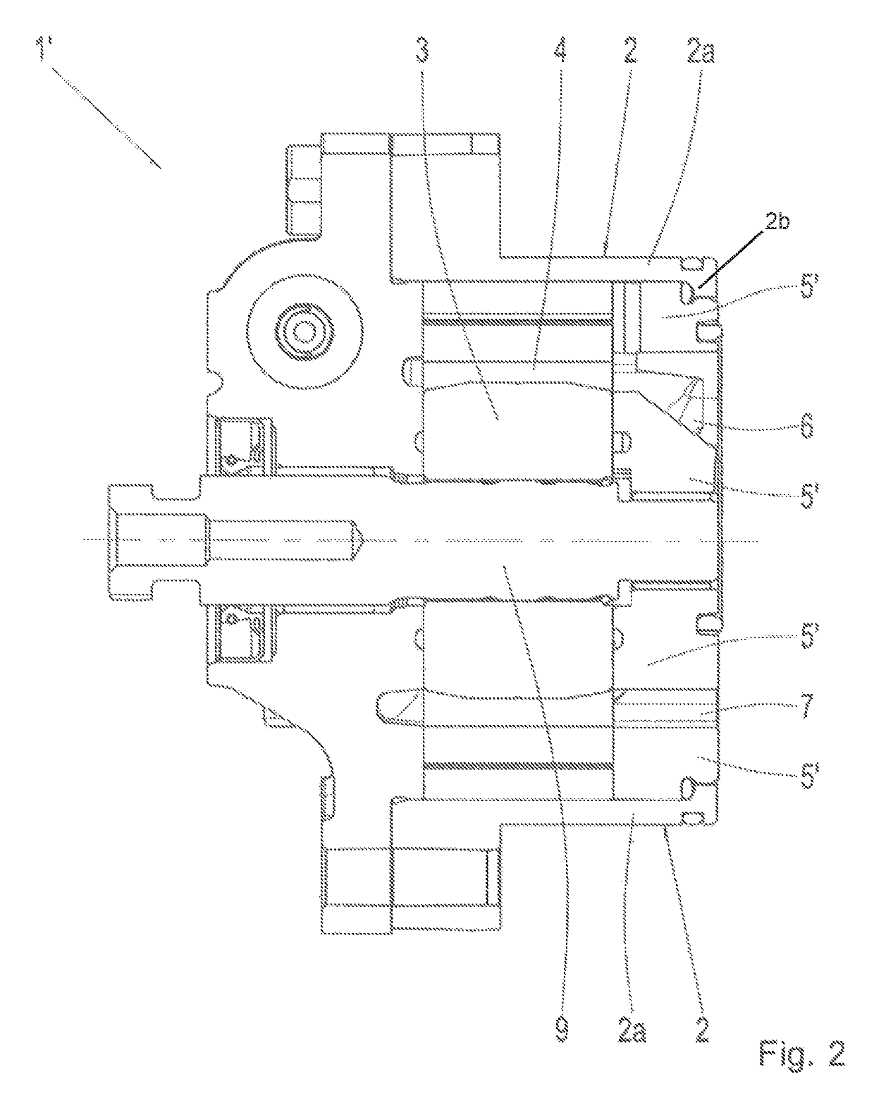
[0008]The design in accordance with example aspects of the invention and the absence of a separate housing bottom increase the thickness of the end plate, by which, in particular, the suction channel is designed to be less steep and is optimized in terms of flow, since the flow deflection is less strong. In this manner, the filling of the pump is optimized. Furthermore, by increasing the thickness of the end plate, the strength of the end plate is increased in an advantageous manner, by which undesirable deformations of the sealing surfaces are largely avoided.

Problems solved by technology

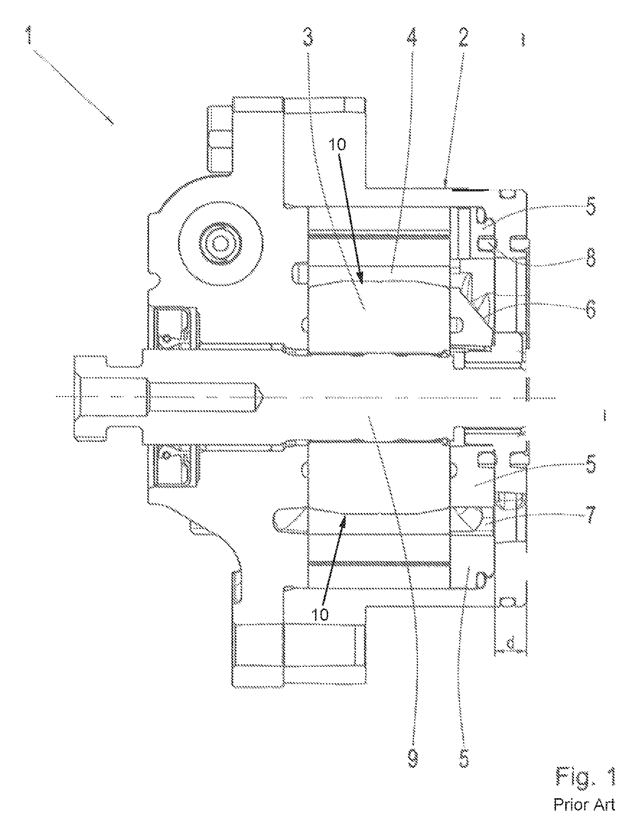
This results in the suction channel being designed to be very steep, by which the oil flow is strongly deflected, which disadvantageously results in unfavorable flow conditions.

Method used


Image

  • Vane pump
  • Vane pump

Examples


Embodiment Construction

[0013]Reference will now be made to embodiments of the invention, one or more examples of which are shown in the drawings. Each embodiment is provided by way of explanation of the invention, and not as a limitation of the invention. For example, features illustrated or described as part of one embodiment can be combined with another embodiment to yield still another embodiment. It is intended that the present invention include these and other modifications and variations to the embodiments described herein.

[0014]Vane cell pumps are well-known to the specialist, such that, within the framework of the following description of figures, only the components relevant to the invention are described and explained. Identical reference signs designate identical components.

[0015]In the attached FIG. 1, the reference sign 1 designates a vane cell pump according to the state of the art, whereas the housing of the pump, which also extends in the bottom area, is provided with the reference sign 2....


PUM


Abstract

A vane cell pump for a transmission of a motor vehicle includes a housing. A rotor defines a plurality of slots. The plurality of slots runs radially. A plurality of vanes is arranged in the plurality of slots of the rotor. An end plate is positioned in a bottom area of the housing. The end plate is configured as a fluid guide with a suction channel and a pressure channel. The end plate forms a bottom wall of the housing.

Description

FIELD OF THE INVENTION[0001]The present invention relates generally to a vane cell pump, in particular for a transmission of a motor vehicle.BACKGROUND[0002]From the state of the art, with automatic transmissions, using hydraulic pumps (such as vane cell pumps) is known; hydraulic pumps make available the hydraulic pressure required for the operation of the transmission and the required conveying volume of the hydraulic control, by which the cooling and lubrication of the transmission and the actuation of the shifting elements of the transmission can be ensured.[0003]In particular, with automatic transmissions of vehicles, using vane cell pumps, with which the vanes are arranged in slots of the rotor of the pump, is known; the vanes can move freely in the radial direction, are rotated along with the rotor and, through centrifugal force under rotational speed and through pressure oil, are applied, at the rear side of the vane (rear vane support), on the lifting ring of the pump or ar...

Claims


Application Information

Patent Timeline
Patent Type & Authority Patents(United States)
IPC IPC(8): F03C2/00F04C15/00F04C2/344F04C15/06F04C2/00F04C18/00
CPCF04C2/344F04C15/06F04C15/0023F04C2240/30F04C2/3448
Inventor FIRZLAFF, UWEMICHEL, CHRISTIANPOHNLEIN, FLORIANCSAJAGI, STEFAN
Owner ZF FRIEDRICHSHAFEN AG
Learn More