Dual parallel hydraulic actuator

a hydraulic actuator and parallel technology, applied in the direction of sliding valve, valve details, valve operating means/releasing devices, etc., can solve the problems of actuator not being able to operate the valve, failure of the secondary piston, complex and redundant system, etc., and achieve the effect of creating redundancy

Active Publication Date: 2019-04-30
AKER SOLUTIONS AS
View PDF19 Cites 1 Cited by
  • Summary
  • Abstract
  • Description
  • Claims
  • Application Information

AI Technical Summary

Benefits of technology

[0019]The dual parallel hydraulic actuator has two totally independently operable pistons, both a mechanically independent system and a hydraulically independent system. The actuator can be operated by using any of the hydraulic chamber, creating redundancy.
[0020]Any failure on the primary system will not prevent the secondary from working properly as a backup. Thus, this invention is more robust and guarantees a safe backup actuation mode. A failure on one of the pistons will therefore not affect the function of the other.

Problems solved by technology

All these valves are controlled hydraulically by a very complex and redundant system.
A mechanical failure in the primary piston or in one of the primary pistons can also cause failure in the secondary pistons.
As an example, if the primary piston jams or there is a scratch in the sealing surface there will be a leakage between the primary piston and the secondary piston and the actuator will not be able to operate the valve.
As the technology moves forward and the HSE requirements in the offshore business become more strict, the scenario where operators are manually operating the surface flow tree while in motion and operation is not allowed.

Method used


Image

  • Dual parallel hydraulic actuator
  • Dual parallel hydraulic actuator
  • Dual parallel hydraulic actuator

Examples


Embodiment Construction

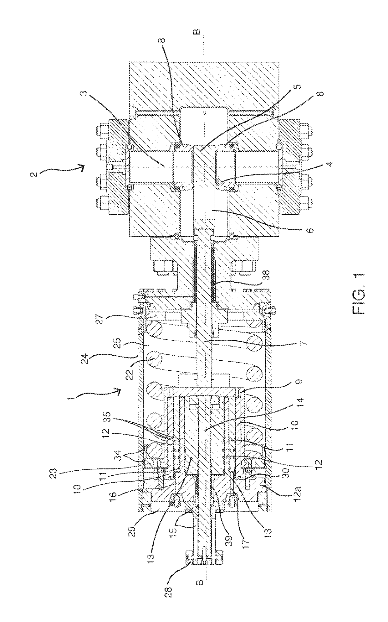
[0033]FIG. 1 shows an actuator 1 connected to a gate valve 2. The actuator 1 is adapted to open and close the gate valve 2.

[0034]In the figure, the actuator 1 is shown in a retracted position. This means that no piston is energized.

[0035]The retracted position of the actuator causes the gate valve 2 to be in a closed position. There is no flow through a cylindrical passage 3 in the gate valve 2 from the upstream side to a downstream side. A gate 4 in the gate valve 2 is in this position blocking the flow path with a solid portion 5 of the gate 4.[0036]The gate valve 2 shown in the figure is a conventional gate valve 2 with annular seats 8 on the upstream side and the downstream side of the gate valve 2 surrounding the passage 3. These seats 8 are abutting the solid portion 5 of the gate 4 when the gate 2 is in closed position

[0037]The gate 4 further comprises a circular opening 6 with substantially the same dimension as the diameter of the passage 3 in the gate valve 2. The gate val...


PUM


Abstract

The invention relates to agate valve hydraulic actuator, said actuator comprising a cup shaped sleeve (9) which is operably coupled to an opening or closing element (5) of the gate valve (2), the actuator further comprising a movable primary piston (13) arranged within a primary cylinder (12) arranged at the inside of the cup-shaped sleeve (9), said primary piston (13) being con figured to move the sleeve (9) and hence said opening and closing element (5) towards an open or closed position of the gate valve (2) by a force applied to the primary piston (13). The hydraulic actuator is distinctive in that it further comprising a movable secondary piston (11) arranged within a secondary cylinder (10) arranged at the inside of the cup shaped sleeve (9), said secondary piston (11) being configured to move the sleeve (9) to the same position of the gate valve (2) as the primary piston by a force applied to the secondary piston in case of failure of the primary piston (13), said primary piston (13) and secondary piston (11) are independently operable of each other.

Description

FIELD OF THE INVENTION[0001]The invention relates to a dual hydraulic actuator and particularly a dual parallel hydraulic actuator with totally independent piston arrangements.TECHNICAL BACKGROUND OF THE INVENTION[0002]This technology are applicable in actuators both subsea and topside to increase the reliability and redundancy of the workover and XMT system.[0003]This actuator design is particularly useful in the Surface Flow Tree (SFT) in open water workover systems. In a workover system, several valves' control systems are connected to each other in order to sequentially close down a test-producing oil well in case of both normal operation procedure and in case of an emergency. All these valves are controlled hydraulically by a very complex and redundant system. The Surface flow tree is positioned on top of the riser, topside in the workover vessel above the drill floor. The tension system on the vessel is connected to the surface flow tree and provides tension and heave compensa...

Claims


Application Information

Patent Timeline
Patent Type & Authority Patents(United States)
IPC IPC(8): F16K31/00F16K31/122F16K3/02F15B20/00F15B15/14
CPCF16K3/0254F16K31/1221F16K31/1225F15B2211/8757F15B20/00F15B2211/864F15B15/1409F16K3/30F16K3/00
Inventor FERREIRA, VICTOR RODRIGUEZNEWLANDS, NICHOLAS
Owner AKER SOLUTIONS AS
Why Eureka
Try Eureka