
System for collision detection and obstacle avoidance

a technology of collision detection and obstacle avoidance, applied in the field of collision detection and avoidance, can solve problems such as increased recall and precision, obstacles are said to have occurred, and obstacles are seen

Active Publication Date: 2019-04-30
HRL LAB
View PDF2 Cites 5 Cited by
  • Summary
  • Abstract
  • Description
  • Claims
  • Application Information

AI Technical Summary

Benefits of technology

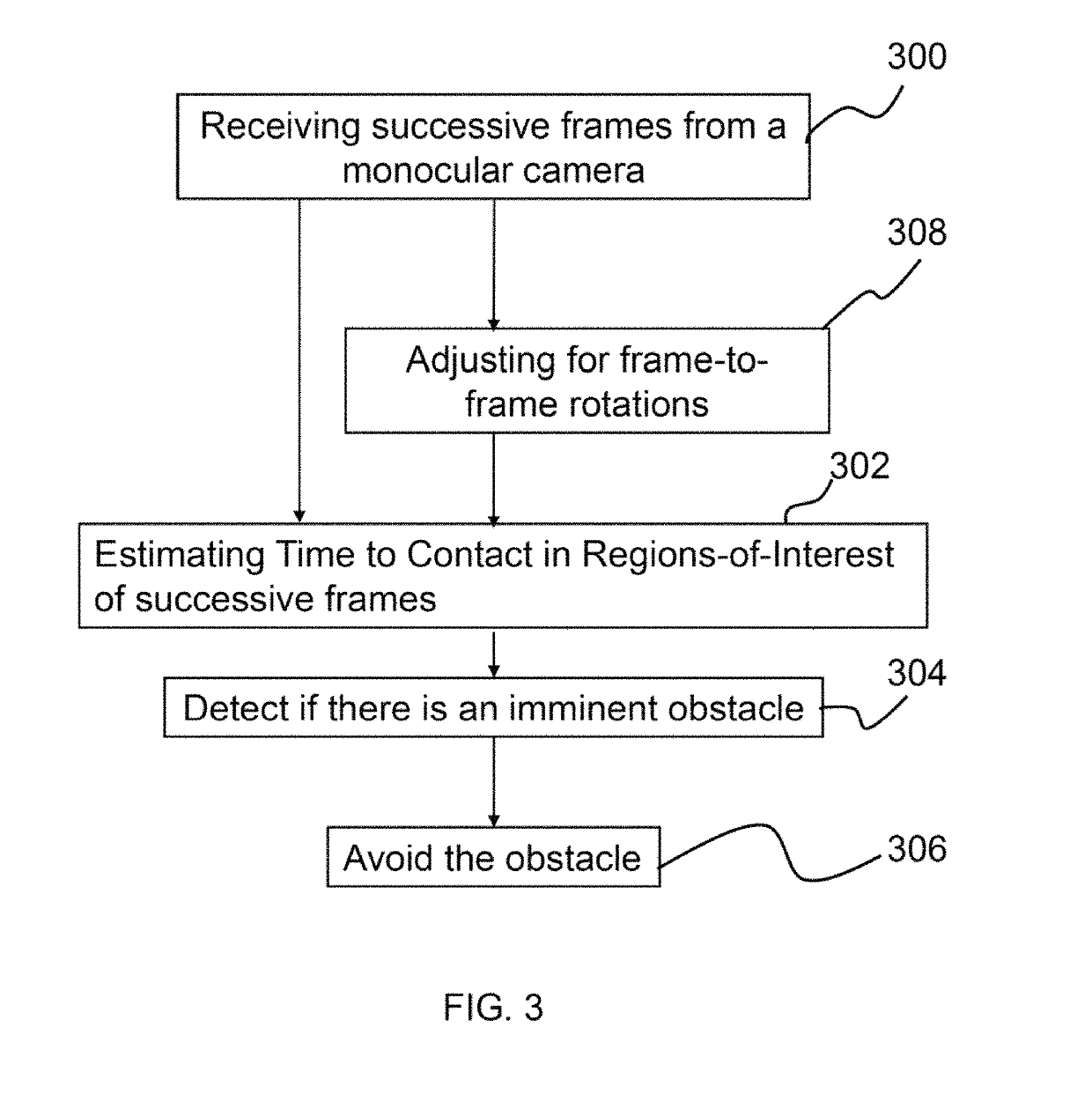
This patent is about a system for detecting and avoiding collisions. It uses a camera to capture images and a computer processor to analyze them. The system can estimate the time it will take for an obstacle to touch a platform, detect if an obstacle is approaching, and determine a path to avoid the obstacle. The system also adjusts the images to compensate for camera rotation. The system can detect the center of the obstacle and determine a path based on the movement of the obstacle in previous images. Overall, the system uses advanced technology to improve safety and efficiency in avoiding collisions.

Problems solved by technology

An obstacle is said to have occurred if the TTC values are basically low enough for a certain period of time.
On the other hand, if p is close to 0, the assumption is made that the unsafe TTC measurements are not very noisy and that with almost any unsafe TTC measurement an obstacle is seen.
Increasing p decreases false negatives, but increases recall and precision and causes more false negatives.
Decreasing p decreases the number of false negatives but drops the recall and precision rates, increasing the number of false positives.
When unsafe_threshold is high it means that collisions are more easily announced.
When unsafe_threshold is low it means that collisions are less easily announced.

Method used


Image

  • System for collision detection and obstacle avoidance
  • System for collision detection and obstacle avoidance
  • System for collision detection and obstacle avoidance

Examples


Embodiment Construction

[0022]The present invention relates to a system for collision detection and avoidance and, more particularly, to a system for collision detection and avoidance estimation using sub-region based optical flow through use of a monocular camera. The following description is presented to enable one of ordinary skill in the art to make and use the invention and to incorporate it in the context of particular applications. Various modifications, as well as a variety of uses in different applications will be readily apparent to those skilled in the art, and the general principles defined herein may be applied to a wide range of aspects. Thus, the present invention is not intended to be limited to the aspects presented, but is to be accorded the widest scope consistent with the principles and novel features disclosed herein.

[0023]In the following detailed description, numerous specific details are set forth in order to provide a more thorough understanding of the present invention. However, i...


PUM


Abstract

Described is a system for collision detection and avoidance estimation using sub-region based optical flow. During operation, the system estimates time-to-contact (TTC) values for an obstacle in multiple regions-of-interest (ROI) in successive image frames as obtained from a monocular camera. Based on the TTC values, the system detects if there is an imminent obstacle. If there is an imminent obstacle, a path for avoiding the obstacle is determined based on the TTC values in the multiple ROI. Finally, a mobile platform is caused to move in the path as determined to avoid the obstacle.

Description

GOVERNMENT RIGHTS[0001]This invention was made with government support under U.S. Government Contract Number SYNAPSE HR0011-09-C-0001. The government has certain rights in the invention.CROSS-REFERENCE TO RELATED APPLICATIONS[0002]This is a non-provisional patent application of 62 / 221,523, filed on Sep. 21, 2015, the entirety of which is hereby incorporated by reference.BACKGROUND OF INVENTION(1) Field of Invention[0003]The present invention relates to a system for collision detection and avoidance and, more particularly, to a system for collision detection and avoidance estimation using sub-region based optical flow through use of a monocular camera.(2) Description of Related Art[0004]Obstacle detection and avoidance is a crucial task that is required to realize autonomous robots. Some robotic systems utilize powerful sensors, such as Light Detection and Ranging (LiDAR) or Radio Detection and Ranging (RADAR) sensors (See the List of Incorporated Literature References, Literature Re...

Claims


Application Information

Patent Timeline
Patent Type & Authority Patents(United States)
IPC IPC(8): G06K9/00G06T7/20G06T7/00G06K9/20H04N7/18G05D1/00G06V20/13G06V20/17
CPCG06K9/00805G06K9/2054G06T7/0024G06T7/2066H04N7/183G05D1/0088G06T2207/10016B64C2201/024G05D1/101H04N7/188G06T7/30G06T7/269G06V20/13G06V20/17G06V20/58B64U10/80
Inventor NUERNBERGER, BENJAMINKHOSLA, DEEPAKKIM, KYUNGNAMCHEN, YANGMONTERROZA, FREDY
Owner HRL LAB
Learn More