ULF/VLF power line communications coupler

a power line communication and coupler technology, applied in the direction of powerline communication systems, signal transmission/receiving via power distribution, power distribution line transmission, etc., can solve the problem of extremely difficult load for vcvs amplifiers, line impedance in the ulf/vlf bands, and capacitor requirements that are too large to fit within a residential electric meter

Active Publication Date: 2019-04-30
PLASCON PACKAGING INC +1
View PDF1 Cites 0 Cited by
  • Summary
  • Abstract
  • Description
  • Claims
  • Application Information

AI Technical Summary

Benefits of technology

[0009]The coupler eliminates the need for large coupling capacitors, allows arbitrary waveforms to be injected into a power line, isolates the power amplifier with which the coupler is associated from 50 / 60 Hz power line signals, provides a relatively high load impedance, and allows use of common off-the-shelf (COTS) VCVS amplifiers such as audio amplifiers for use in creating PLC signals.

Problems solved by technology

In addition, the power line impedance in the ULF / VLF bands is so low that it presents an extremely difficult load for VCVS amplifiers.
With regard to capacitive coupling, it has been found that for ULF and VLF band signals, the capacitor required may be too large to fit within a residential electric meter.
With regard to switched load transmitters, it has been found they are limited as to the possible signals they can be used to transmit.
For example, arbitrary waveform generation is not possible with these transmitters.

Method used


Image

  • ULF/VLF power line communications coupler
  • ULF/VLF power line communications coupler
  • ULF/VLF power line communications coupler

Examples


Embodiment Construction

[0023]The following detailed description illustrates the invention by way of example and not by way of limitation. This description clearly enables one skilled in the art to make and use the invention, and describes several embodiments, adaptations, variations, alternatives and uses of the invention, including what is presently believed to be the best mode of carrying out the invention. Additionally, it is to be understood that the invention is not limited in its application to the details of construction and the arrangement of components set forth in the following description or illustrated in the drawings. The invention is capable of other embodiments and of being practiced or carried out in various ways. Also, it will be understood that the phraseology and terminology used herein is for the purpose of description and should not be regarded as limiting.

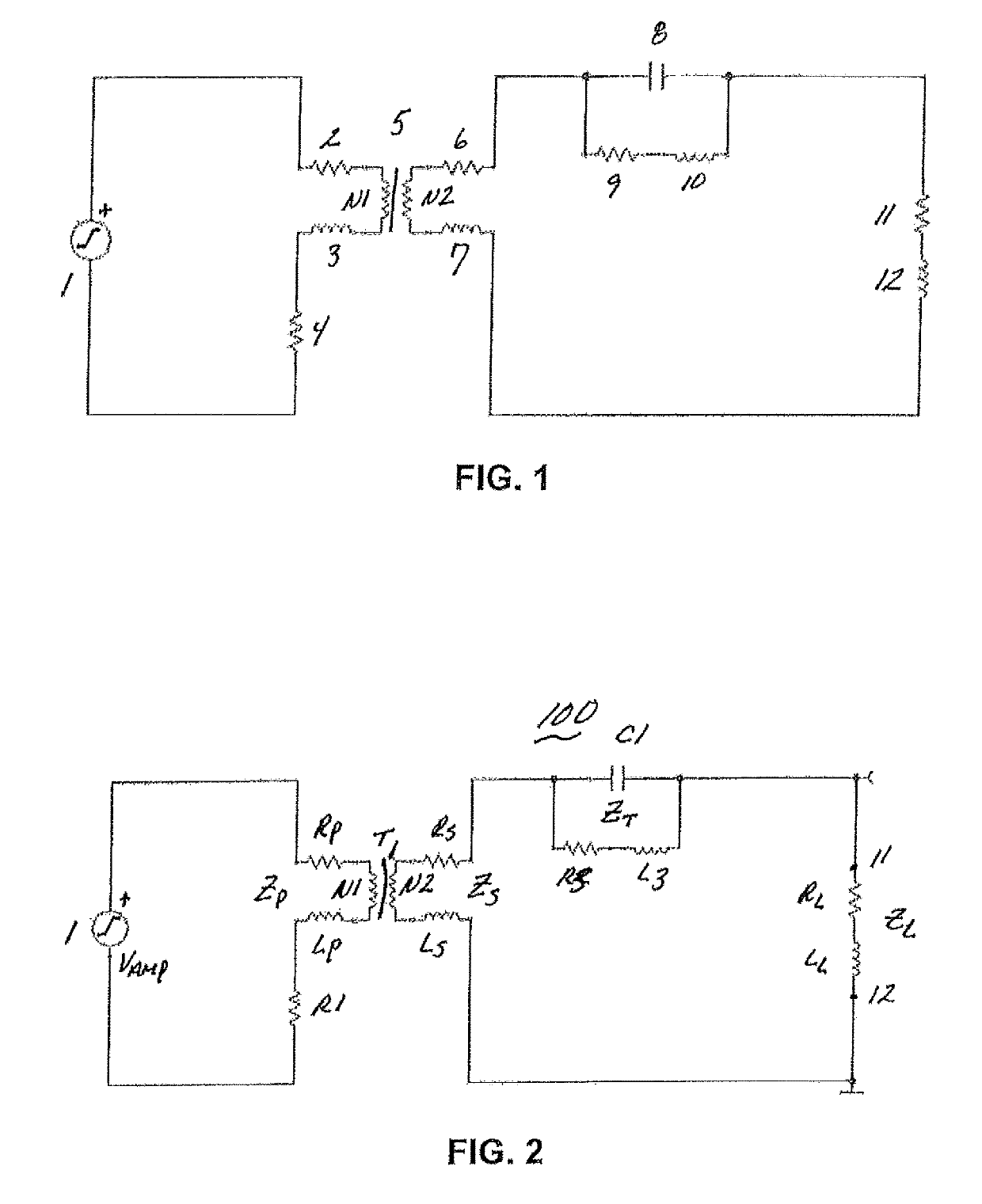
[0024]In the present invention, a coupler 100 is implemented in an electrical circuit including a COTS VCVS amplifier (e.g., an au...


PUM


Abstract

A circuit (100) for coupling an amplifier (1) in an electrical power distribution system with the amplifier electrically and physically isolated from a power line of the system. The amplifier generates arbitrary signal waveforms injected into the power line. A transformer (T1) has a primary and a secondary side with the amplifier located on the primary side and the secondary side connected to the power line. A resistor (R1) series connected with the primary side of the transformer is sized to accommodate a minimum load impedance of the amplifier and minimize power dissipation. A resonant circuit interposed between the secondary side of the transformer and the power line has values for a capacitor (C1) and an inductor (L3) forming the resonant circuit chosen to peak the amplitude of the arbitrary signal waveform at the frequency of a waveform propagated through the power line.

Description

[0001]This application derives and claims priority from U.S. provisional application 62 / 552,629 filed Aug. 31, 2017 which is incorporated herein by reference.BACKGROUND OF THE INVENTION[0002]Power line communications (PLC) relates to the transmission of messages and data between a utility site and a customer site using the same lines over which electricity is conducted through the utility's power grid from the one point to the other. Communications are routed in both directions over the grid and can include instructions for configuring equipment (loads) at a site, data with respect to energy availability or usage, or reports as to the current status of operations at a site.[0003]Typically, PLC occurs at frequencies of between 3 kHz and 500 kHz, or between 1.8 MHz and 250 MHz. In PLC systems, repeaters are often employed to extend the range of communications.[0004]By contrast, Ultra Low Frequency (ULF) and Very Low Frequency (VLF) PLC occur at frequencies between approximately 500 Hz...

Claims


Application Information

Patent Timeline
Patent Type & Authority Patents(United States)
IPC IPC(8): H04B3/56
CPCH04B3/56H04B2203/5483H04B2203/5404
Inventor BERCHIN, GREGORYYANEY, DAVID
Owner PLASCON PACKAGING INC
Why Eureka
Try Eureka